86
07-02-12-02-EN-V1215.doc / Type: 638
9.2 Safe Torque Off Function, (STO)
General
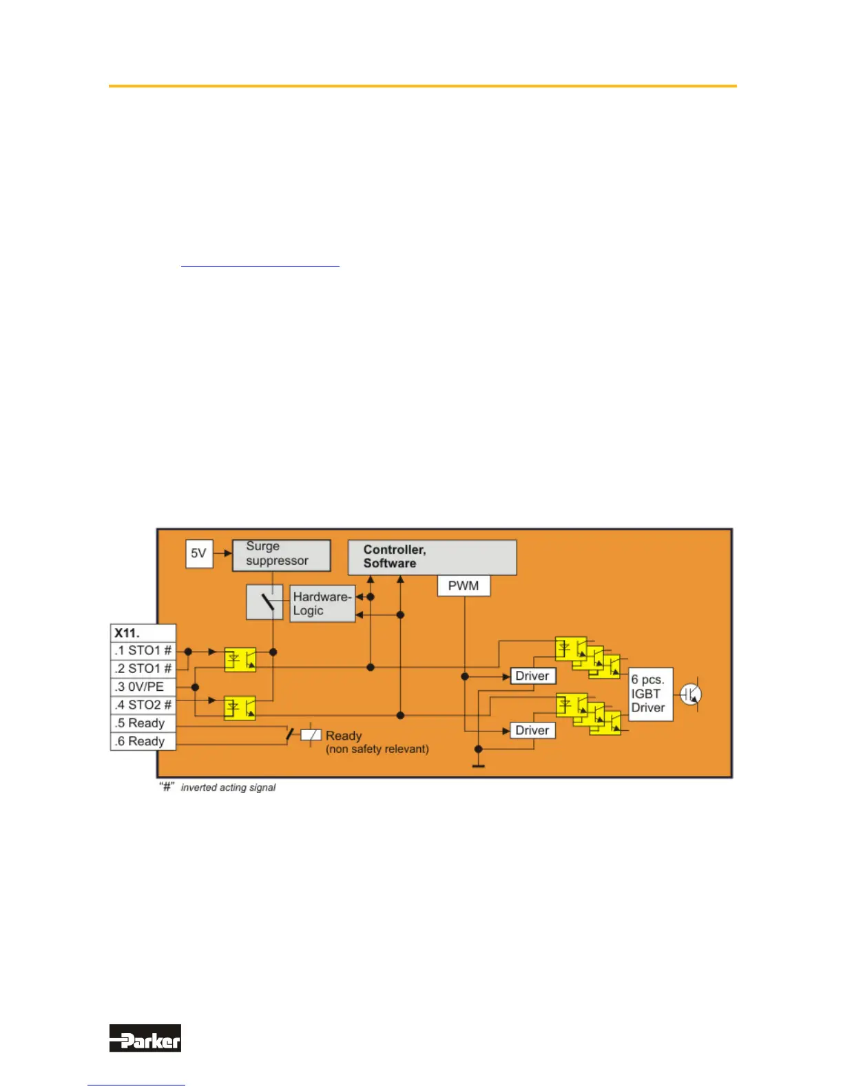
The electricity flow to the motor windings is controlled through a solid state power component bridge
(6-times IGBT). A microprocessor switch with PWM logic switches the IGTB’s rotating field
orientation. Optical couplings are employed between the control logic and the power unit to provide
for electrical isolation.
The X11 Connector Plug (STO) is located on the front of the drive unit. This connector plug is
controlled utilizing two optical couplings which communicate over two channels through terminals
STO1# and STO2#, and which in a controlled condition supplies the PWM optical coupler with control
of the solid state power component.
A test takes place to determine the condition of the input channels. Within the given window of time
the condition of both channels must be identical. In the event that a fault condition exists,
(different signals from STO1# and STO2#), then the coupling power supply is shut-off and a signal is
sent to the 7 segment display.
The re-activation of the power supply to the coupling is then only possible by performing
a hardware reset, by turning the equipment off and then back on again.
In addition to the description of the hardware based shut-off through the two channel communication,
the internal unit processor provides for a software based shutdown of the PWM circuit.
The PWM circuit can be set for time delayed activation, after the recognition of the activation of both
STO inputs, through the programming of the safety parameters for the active time delay.
● Block Circuit Diagram

 Loading...


