6 Wiring Instructions
Wiring InstructionsWiring Instructions
Wiring Instructions
07-02-12-02-EN-V1215.doc / Type: 638
67
6 Wiring Instructions
6.1 Electromagnetic Compatibility (EMC)
Conformity, in accordance with the EG-EMC Directive 2004/108/EC has been evaluated using a
reference system, consisting of a compact type drive and a line-filter on mounting-plate, connected
to an AC-synchronous motor. The motor cable is mainly responsible for EMC emissions. The motor
cable must be installed therefore employing exceptional care. The layout of grounding is very
important. Grounding has to be low-impedance for high frequencies. That means, all ground
connecting parts have to be connected over a large surface contact area. The measurements
provided are valid only with the use of our cables, suppression aids and line filters and by
application
of the following wiring instructions:
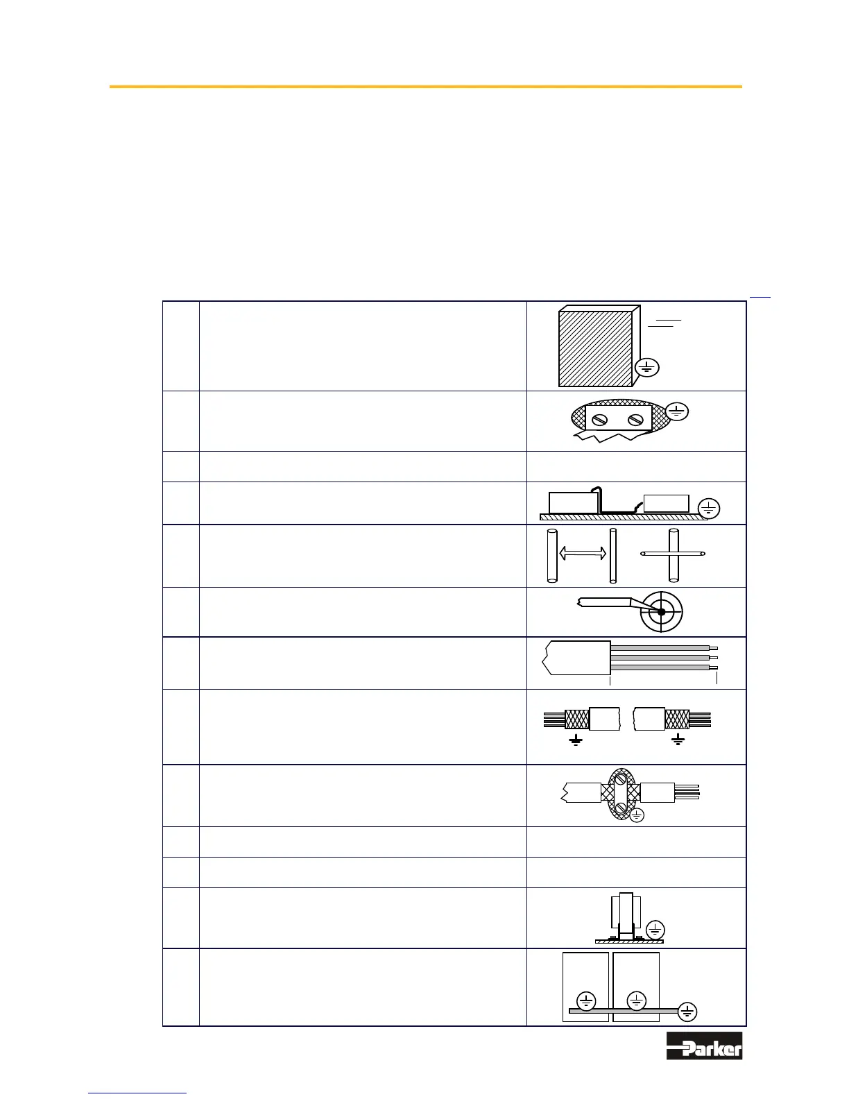
● Hints for Mounting
A
All components are mounted inside of
a steel control cubicle on a mounting plate
(min. thickness 3mm).
Recommended: Galvanized
3mm
B
The connection between the drive housing, the filter
housing and the mounting plate must be bare metal
and not reduced by varnish.
All screws must be properly tightened !
C
Use only our filters and cables for motor and
resolver connections.
D
Place all wires and cables as close as possible to
grounded metal parts.
E
Separate power and control cables.
Minimum distance: 0,3m
Cross Points: 90°
0,3 m
90°
F
Avoid cable loops. The run between the line-filter and
drive has to be as close and short as possible (drilled).
G
Maintain the shielding as close as possible to the
cable-end (max distance 8 cm).
8 cm max
H
Connect shielded connections according to general
view of connections: See chapter 2.1. Ground shielding
on both sides, with the shortest possible cable run.
For long cables: Connect additional shielded areas
along the way.
I
Connect the shielded area to well grounded points.
K
Connect unused wires in cables to the ground.
L
Install control cables close to grounded metal parts or
shielding when leaving the control cubicle
M
Pay close attention to the grounding of control-
transformer (DC 24V). Use a transformer with a metal
socket and pay attention to provide for good conductive
contact on mounting plate.
N
Pay close attention to the overall grounding of the
complete system. Interconnect several mounting plates
using copper rails or copper band. Pay attention to the
ground connection between the control cabinet and the
This manual was downloaded on www.sdsdrives.com
+44 (0)117 938 1800 - info@sdsdrives.com

 Loading...


