2 Connection Assignments and Functions
Connection Assignments and FunctionsConnection Assignments and Functions
Connection Assignments and Functions
38
07-02-12-02-EN-V1215.doc / Type: 638
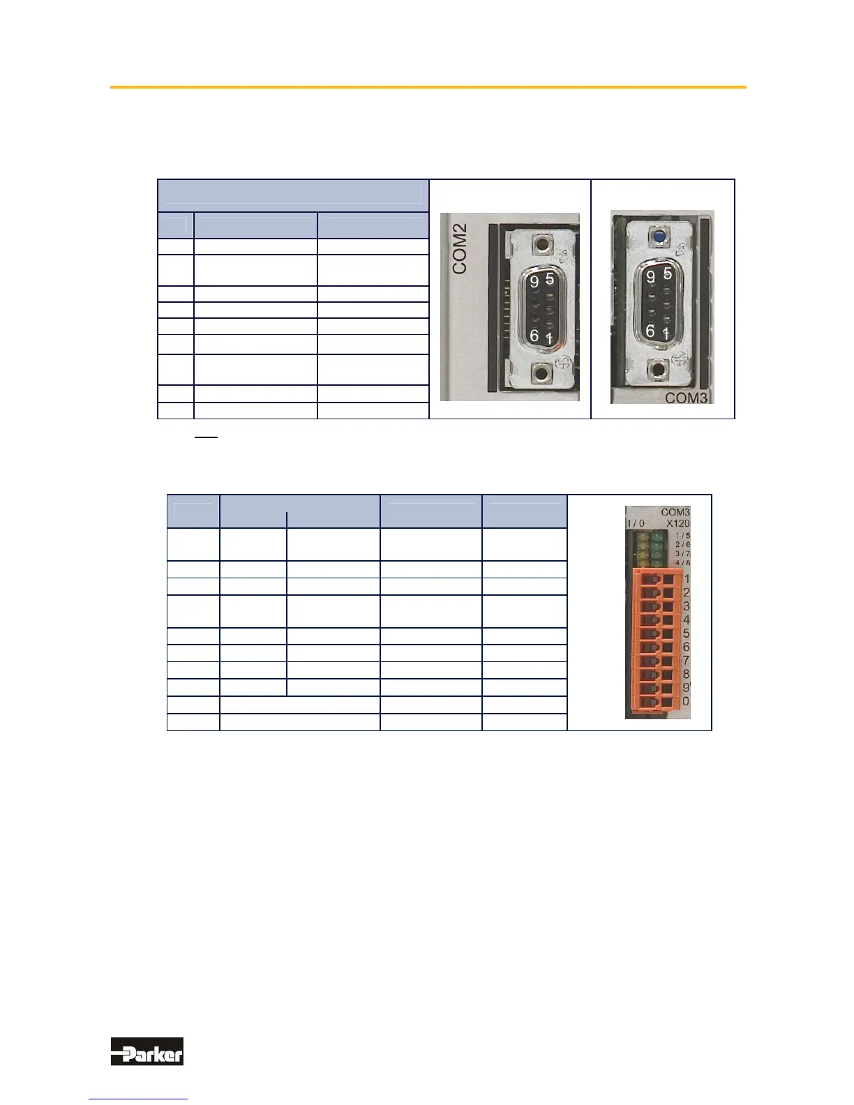
2.11 Fieldbus Interface RP 2CA, 2C8
● Pinning CAN1-BUS and CAN2-BUS
Module: RP 2CA, 2C8
CAN1
CAN2
PIN
Function Designation
1 - -
2
CAN_L Bus Line
(dominant low)
CAN_L
3 Ground CAN-GND
4 - -
5 - -
6
Optional Ground
CAN-GND
7
CAN_H Bus Line
(dominant high)
CAN_H
8
-
-
9 - -
with galvanic isolation
● Pinning RP 2C8 X120 (with I/O’s)
X120
Function
BIAS PIN Status
I/O’s
0 1
1 BIAS
Reset
Drive Fault
Input 121 Input
2 BIAS
Limit Switch +
Input 122
Input
3 BIAS
Limit Switch - Input 123
Input
4 BIAS
Reference
Switch
Input 124
Input
5 BIAS Cam 1
Output 125 Output
6 BIAS Cam 2
Output 126 Output
7 BIAS Cam 3
Output 127 Output
8 BIAS Cam 4
Output 128 Output
9
Ext. +24 V Supply -
Ub
10
Ground Reference 0 V -
B
The signal status of the I/O’s is shown with a 2mm LED
LED on I/O = high / LED off I/O = low.
(min./max. cable cross-section: 0,08mm² / 1,5mm²)
This manual was downloaded on www.sdsdrives.com
+44 (0)117 938 1800 - info@sdsdrives.com

 Loading...


