2 Connection Assignments and Functions
Connection Assignments and FunctionsConnection Assignments and Functions
Connection Assignments and Functions
36
07-02-12-02-EN-V1215.doc / Type: 638
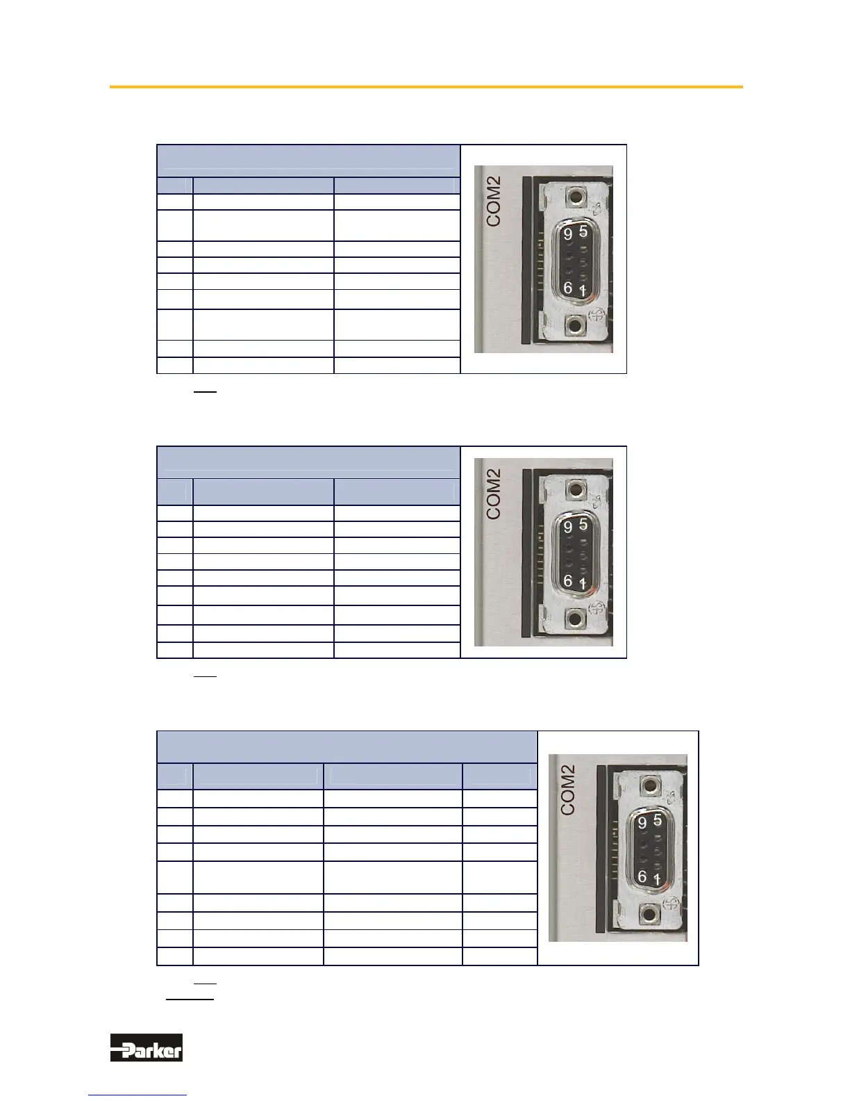
● Pinning for CAN
Module: RP CAN (CAN BUS1)
PIN
Function Designation
1 - -
2
CAN_L Bus Line
(dominant low)
CAN_L
3 Ground CAN-GND
4 - -
5 - -
6
Optional Ground CAN-GND
7
CAN_H Bus Line
(dominant high)
CAN_H
8
- -
9 - -
with galvanic separation
● Pinning for Profibus DP
Module: RP PDN
PIN
Function Designation
1 - -
2 - -
3 Line B B
4 Request to Send RTS
5 Ground PDP-GND
6
Potential +5V
+5V
7
-
-
8
Line A
A
9 - -
with galvanic separation
● Pinning for EA5 I/O-Interface (Digital In and Outputs)
Module: RP EA5
PIN
Function Designation Status
1
BIAS Input 101 Standard Input
2
BIAS Input 102 Standard Input
3
BIAS Input 107 Standard Input
4
BIAS Input 108 Standard Input
5
0VSPS Ground reference
0VSPS
6
BIAS Input 106 Standard Input
7
BIAS Output 109 Standard Output
8
BIAS Output 110 Standard
9
+24VSPS Ext. +24V feed-in
with galvanic separation
Notice !
The inputs with the internal numbers 107 and 108 must be connected to pin numbers 3 and 4.
The outputs with the internal numbers 109 and 110 must be connected to pin numbers 7 and 8.
This manual was downloaded on www.sdsdrives.com
+44 (0)117 938 1800 - info@sdsdrives.com

 Loading...


