7 Hardware Configuration
Hardware ConfigurationHardware Configuration
Hardware Configuration
07-02-12-02-EN-V1215.doc / Type: 638
69
7 Hardware Configuration
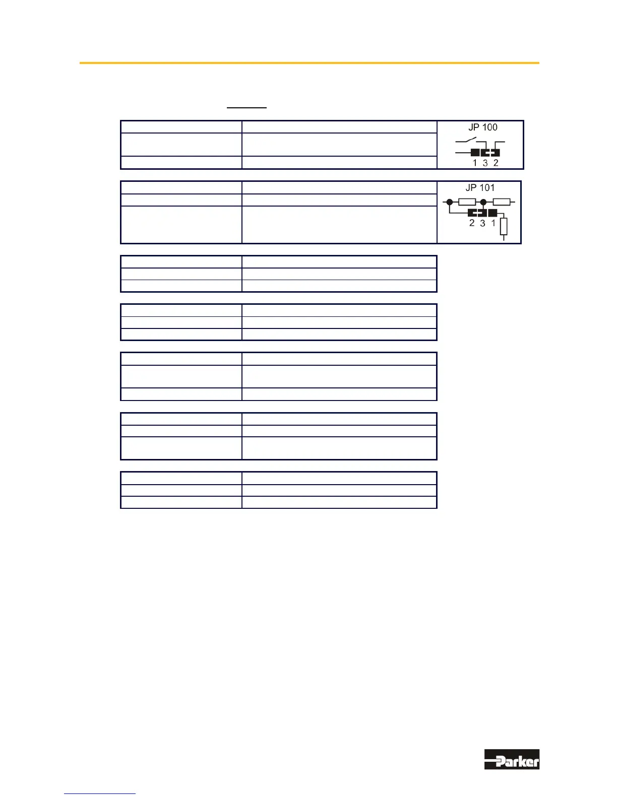
7.1 Jumpers
All jumpers are set to a standard preset !
JP100, Bridged Pad
2 and 3 (standard) READY contact with reference to common
output supply voltage on X10.21
1 and 3 READY contact can be freely wired
JP101, Bridged Pad.
2 and 3 (standard) Analog input X10.19 without internal pull-up.
1 and 3 Analog input X10.19 with internal pull-up
to +12 V
JP1, JP2, Bridged Pad Adjust identically !!
2 and 3 (standard) X10.15 = high active
1 and 3 X10.15 = low active
JP3, JP4, Bridged Pad Adjust identically !
2 and 3 (standard) X10.14 = high active
1 and 3 X10.14 = low active
JP2.8, JP2.3, JP2.7, JP2.2
Open
Default, RP -CAN, -DEV, -2CA, -2C8,-CC8,
-CCA, -PDN, -PC8, -PCA,
Close
RP -232, -422, -485, -IBS, -EA5, -SUC
JP600
Close Default
Open Minimal current leakage with external
filter operation
JP604
Close Default internal brake resistor active
Open internal brake resistor deactive
This manual was downloaded on www.sdsdrives.com
+44 (0)117 938 1800 - info@sdsdrives.com

 Loading...


