62
07-02-12-02-EN-V1215.doc / Type: 638
● Layout of the Ballast Capacity
Energy, which is produced by the electrical brake motor, will be fed into the DC link and then
through the DC link coupling to serve other motors within the sequence. Only a portion of the
energy which is produced in this manner leads to an increase in the DC link voltage and will then,
at a specified voltage threshold, be converted to heat and released through the units’ internal or
external ballast. Therefore, an energy exchange occurs between the units, creating a positive
energy balancing and overall work load balance of the ballast switches. A significant reduction
factor in the load can be anticipated, depending upon the specifics of the installation.
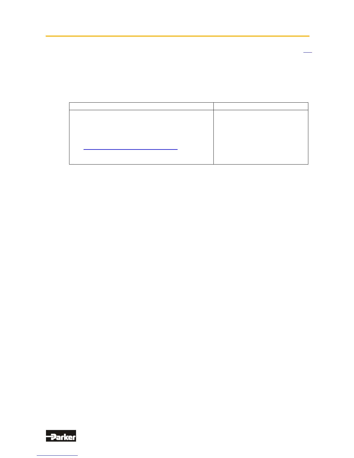
Layout Step by Step (without reduction factors) Remarks
Addition of all internal unit ballast continuous ratings
Addition of all internal unit ballast peak performance
ratings
For information concerning the required data and
design layout of the ballast resistance: See Chapter -
“● Layout of the Ballast Resistance“
Arrange the external ballast resistance with regard
for the braking power occurrence, if possible.
The load on the internal ballast will
be evenly divided between all of the
units connected in parallel.

 Loading...


