2 Connection Assignments and Functions
Connection Assignments and FunctionsConnection Assignments and Functions
Connection Assignments and Functions
30
07-02-12-02-EN-V1215.doc / Type: 638
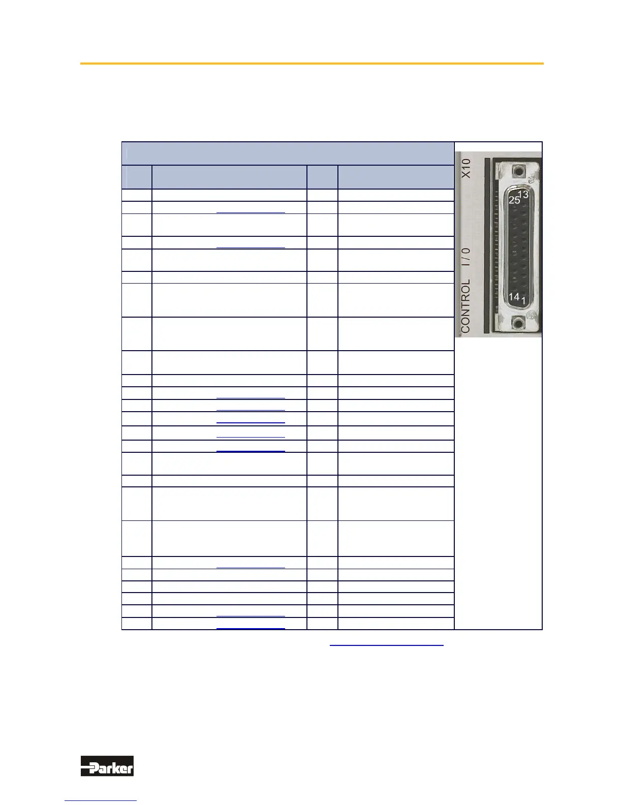
2.7 Signal Connection
● Control Signal Plug X10 (SUB D25 Socket)
Inputs / Outputs
Control Signal Plug X10
PIN
X10
Function Type Description
1
Shielding Connection Screen
2
Configurable (Operating Mode) OPTO
Input
3
Stabilized Auxiliary Supply Voltage
-12VDC; max. 80 mA
Output
Auxiliary Supply Voltage
4
Configurable (Operating Mode) OPTO
Input
5
Reference Point to X10.18 Input Analog
0...+/-10V / Ri = 10 kOhm
6 Configurable - Output Analog
7
Through JP100 (soldered jumper)
assignable as a free and loopable
potential for the READY Contacts
Optional
8
ON: Drive trouble free
OFF: Drive problem or
power supply interruption
Relays
Output
Constant: Ready
9
Reference Point for Digital Input 0V, Reference Point for
Digital Inputs
10
Ground for Analog Signal Ground
11
Configurable (Operating Mode) OPTO
Input
12
Configurable (Operating Mode) OPTO
Output
13
Configurable (Operating Mode) OPTO
Output
14
Configurable (Operating Mode) OPTO
Input
15
Configurable (Operating Mode) OPTO
Input
16
Stabilized Auxiliary Supply Voltage
+12V DC; max 80 mA
Output
Auxiliary Supply Voltage
17 Configurable - Output Analog
18
Speed Setpoint;
Scaleable differential with
respect to X10.5
Input Analog
0...+/-10V / Ri = 10 kOhm
19
Current-Limit; can be activated
and is scaleable
(0..+10V for 0.. I
Input Analog
0..+10V
Ri = 10 kOhm
20
Configurable (Operating Mode) OPTO
Output
21 Nominal: 24VDC Supply for Outputs
22 Configurable (Safety Functions) OPTO
Input
23
- - -
24
Configurable (Operating Mode) OPTO
Input
25
Configurable (Operating Mode) OPTO
Input
Data for the digital in and outputs: See Chapter. “■ General Technical Data“
This manual was downloaded on www.sdsdrives.com
+44 (0)117 938 1800 - info@sdsdrives.com

 Loading...


