07-02-12-02-EN-V1215.doc / Type: 638
117
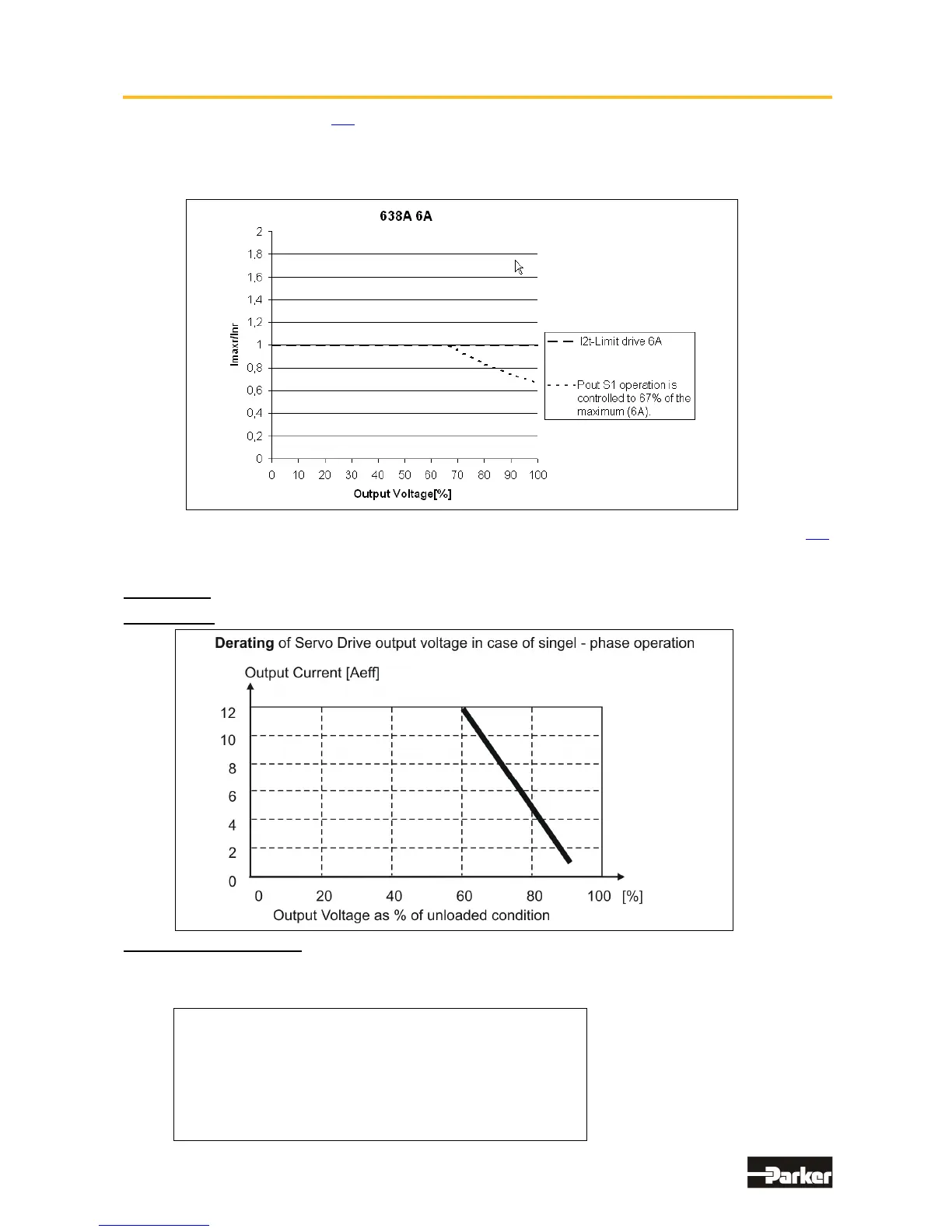
● Output Power 638A
In the event of continuous operation in the full-load range, the limits as shown in the following diagram
need to be respected for the 6A device. If the line supply is singlephase in this condition, a line-choke with
uk>=4% is necessary. For example E12-0018KL. This is valid for the 4A and 6A device.
Typical servo applications are not affected by this restriction. (S3 operation: Start/Stop).
● Singlephase and Threephase supply
Due to the line-ripple of the DC-Bus, the rate of usable output voltage is reduced as follows.
This reduction affects the maximum attainable speed of the applied motor.
Three-phase supply: The unloaded output voltage will be reduced to approx. 90%, maximally 85 %
Single-phase supply: 50 – 60Hz: see following Diagram:
Hint for Parameterization:
To avoid the unexpected tripping of the under voltage threshold, the parameter setting should be left on
the default values (EASYRIDER
®
Windows – Software).
Required motor-terminal-voltage for specified speed.
Approximation: (up to 3000RPM)
Ukl = 1,2 * (EMF * n / 1000) + I * (Rph + RL) [V]
Ukl Required Motor Voltage [V
RMS
]
EMF Back-EMF of Motor [V
RMS
] / 1000 RPM
Rph Resistance of Motor (between terminals) [
Ω]
RL Line Resistance of Motor cable [Ω]
I Motor Current [A
RMS
]

 Loading...


