9 Safe
Safe Safe
Safe Torque
TorqueTorque
Torque
Off (STO)
Off (STO)Off (STO)
Off (STO)
07-02-12-02-EN-V1215.doc / Type: 638
73
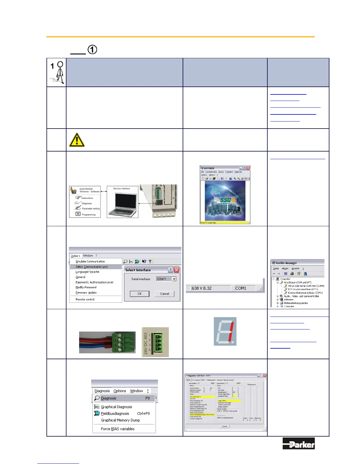
8.2 Step : Wiring and Communications Test
Action, Function Anticipated Result
Remark,
Cause of Fault
Condition
1.1
Before Starting the Equipment!
Check the wiring; in particular:
supply voltage, incoming powerline,
motor wiring, motor polarity,
feedback system, (Resolver; HIPERFACE
®
etc.),polarity Sine / Cosine etc.
-
638 Connector
Assignment
Electrical Installation
Wiring Instructions
Model Code
1.2
First uncouple the motor shaft, before
addressing critical mechanical
problems.
Limitation of potential danger
1.3
Connection of the Diagnostic Interface Link
for the Drive - COM1 RS232 Connection to
the PC and start EASYRIDER Windows
Software.
EASYRIDER for Windows
Software Start side:
EASYRIDER Software
Cable Interface
USB RS232 Adapter
1.4
Settings for the Connected COM Ports
With the PC in Options
Menu select „Interface Selection“.
The selected COM Port is
shown
on the lower right hand corner
of
the window of the EASYRIDER
for
Windows Software
The available
connections to the PC
are shown in the
Device Manager under
System Control
1.5
Supply Voltage US = 24V DC
through X01-Connection to the system.
7 Segment Display:
Power Supply
Connection X01
7 Segment Display
Symbol:
1.6
Check the communications connections and
functions by utilizing the Diagnosis window or
by employing the F9 button on the keyboard.
EASYRIDER Diagnosis
Window:
It is always the last
window where settings
have been made
which will be opened!
This manual was downloaded on www.sdsdrives.com
+44 (0)117 938 1800 - info@sdsdrives.com

 Loading...


