07-02-12-02-EN-V1215.doc / Type: 638
123
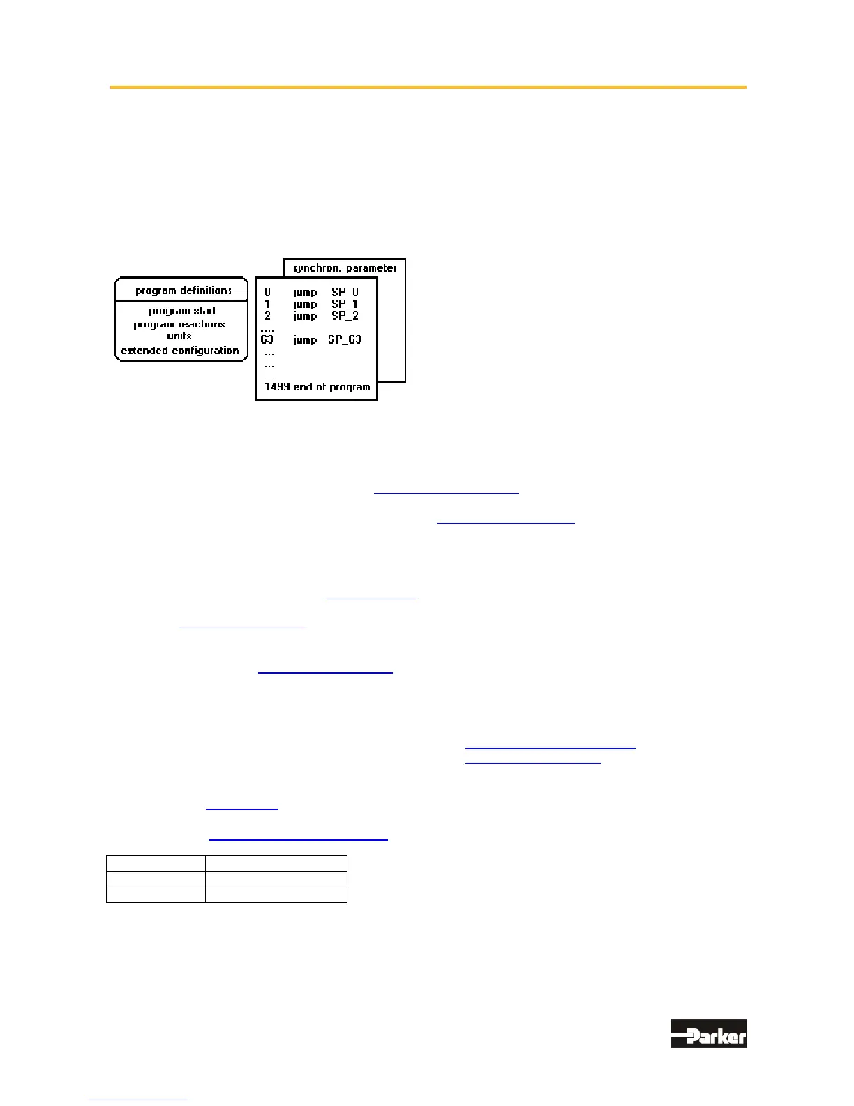
● Program layout
A BIAS program consists of 3 basic memory areas.
1. The program definition:
contains all definitions for starting and processing a BIAS program, the entries for defining a unit for
position presetting and the necessary configurations of the inputs and outputs.
2. The command memory:
contains up to 1500 BIAS commands.
3. The synchronous parameters:
contain the definitions for the 16 synchronous profile blocks and the 2048 supporting points.
The basic memory areas are part of the BIAS program.
In the EASYRIDER for Windows Software the extension is *.WBD.
● Execute a BIAS program
With the selection of the default values in the BIAS program definitions the BIAS processing is started in
operating mode 5 ”position control with BIAS processing” after activating the output stage of the regulator.
The first BIAS block to be executed is determined in the BIAS program definition (Parameter ”program start”).
Alternatively it is possible to select in the BIAS Program definitions the mode “Continue execution at
deactivation from Deactive start” (as of firmware 8.41).
“Deactive start” defines the line number of the first command which is executed first after deactivation
or reset with restart of the drive.
In this case the BIAS interpreter is in protected mode. Drive commands to the power stage are not allowed.
However it is possible to control an other drive with the Multi-axis functionality of the 3 trajectory generators.
Details see BIAS Protected mode.
Normally, the regulator processes one BIAS command sequentially every trajectory cycle.
With the BIAS command “Execute x commands” it is possible to calculate up to 9 commands in one
trajectory cycle.
If the BIAS processing encounters a move command, it can be started with the Low-High slope of the start
input.
Serie Input Configuration
635/ 637/637+/637f/638: X10.11 ”Start input BIAS” (Function 0)
631: X10.9 “Start input ” (Function 3)
Alternatively, move commands are started when the start identifier is set before the move command, via the
BIAS command ”Start axis”.
The following blocks will be processed after a successful start.
If the command, ”Wait for “position reached”” follows a move command, block processing will only be
continued after the target position is reached.
Drive type: Trajectory cycle:
631/635/637 1,899ms
637+/637f/638 0,844ms

 Loading...


