XXX XXX
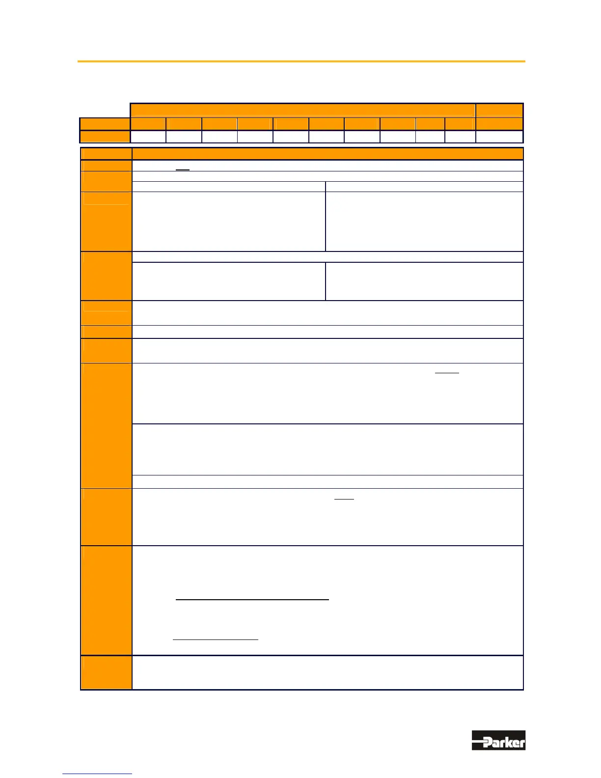
Marking Description
a 638 = 6th. Generation Digital Servo Drive
b
Size:
A = Size A B = Size B
c
Rated Current:
0
1 = 1,0 amps
02 = 2,0 amps
04 = 4,0 amps
06 = 6,0 amps
07 = 7,0 amps
Rated Current:
03 = 2,5 amps
05 = 5,0 amps
08 = 7,5 amps
10 = 10,0 amps
15 = 15,0 amps
d
Intermediate Voltage:
638A
3 = 325 VDC / 230 VAC
638B
3 = 325 VDC / 230 VAC
6 = 565 VDC / 400 VAC
7 = 678 VDC / 480 VAC
e
F = With Integrated Filter = Standard
A = less leakage current (AC-side Y-capacitators deactivated; JP600 open)
f
0 = Without EMC - Clip = Standard
g
Safety Performance:
STO = Safe Torque Off = Standard
h Additional option-module RP -XXX on the drive for communication via COM2
000 = No Option
232 = RS 232 interface ≅ slot A (A, B)
422 = RS 422 interface ≅ slot A (B)
485 = RS 485 interface ≅ slot A (B)
CAN = CAN – Bus ≅ slot A (B)
CCA = 2 x CAN + RS 485 ≅ slot B (A) / [C*]
CC8 = 2 x CAN + 4 outputs and 4 inputs + RS 485 ≅ slot B (A) / [C*]
PDN = Profibus DP ≅ slot B (A)
IPC8 = Profibus DP + CAN2 + 4 outputs and 4 inputs + RS 485 ≅ slot B (A)
PCA = Profibus DP + CAN2 + RS 485 ≅ slot B (A)
EA5 = I/O - Interface (5 inputs, 2 outputs) ≅ slot B (A)
h1
Additional Options Module on the drive via X200
000 = No Option
CCA = 2 x CAN ≅ slot C*]
CC8 = 2 x CAN ≅ slot C*]
EAE = I/O - Interface (14 inputs, 10 outputs) ≅ slot C
i
X300 – Functions Module
RD2 = Standard X30 Resolver – Module 2nd Version = Standard ≅ slot D
HF2 = HIPERFACE – Module 2nd Version ≅ slot D
SC2 = Sine / Cosine - Module 2nd Version ≅ slot D
with Memorychip as of firmware V 8.35
RM1 = Resolver + Memory- Module 2nd Version ≅ slot D
HM1 = HIPERFACE + Memory- Module 2nd Version ≅ slot D
SM1 = Sine/Cosine + Memory- Module 2nd Version ≅ slot D
as of Firmware V 8.44
EM1 = EnDat + Memory- Module ≅ slot D
j
Enter only when used
X7x = Broad-band contact X10.7 - X10.8
BSx = Moisture/Condensation Protection
*Only CAN2 can be employed when utilizing the option module located at slot [C], (internal BUS / COM3 B).

 Loading...


