Parker Hannifin S.p.A Divisione S.B.C. user’s manual TWIN-N and SPD-N
108
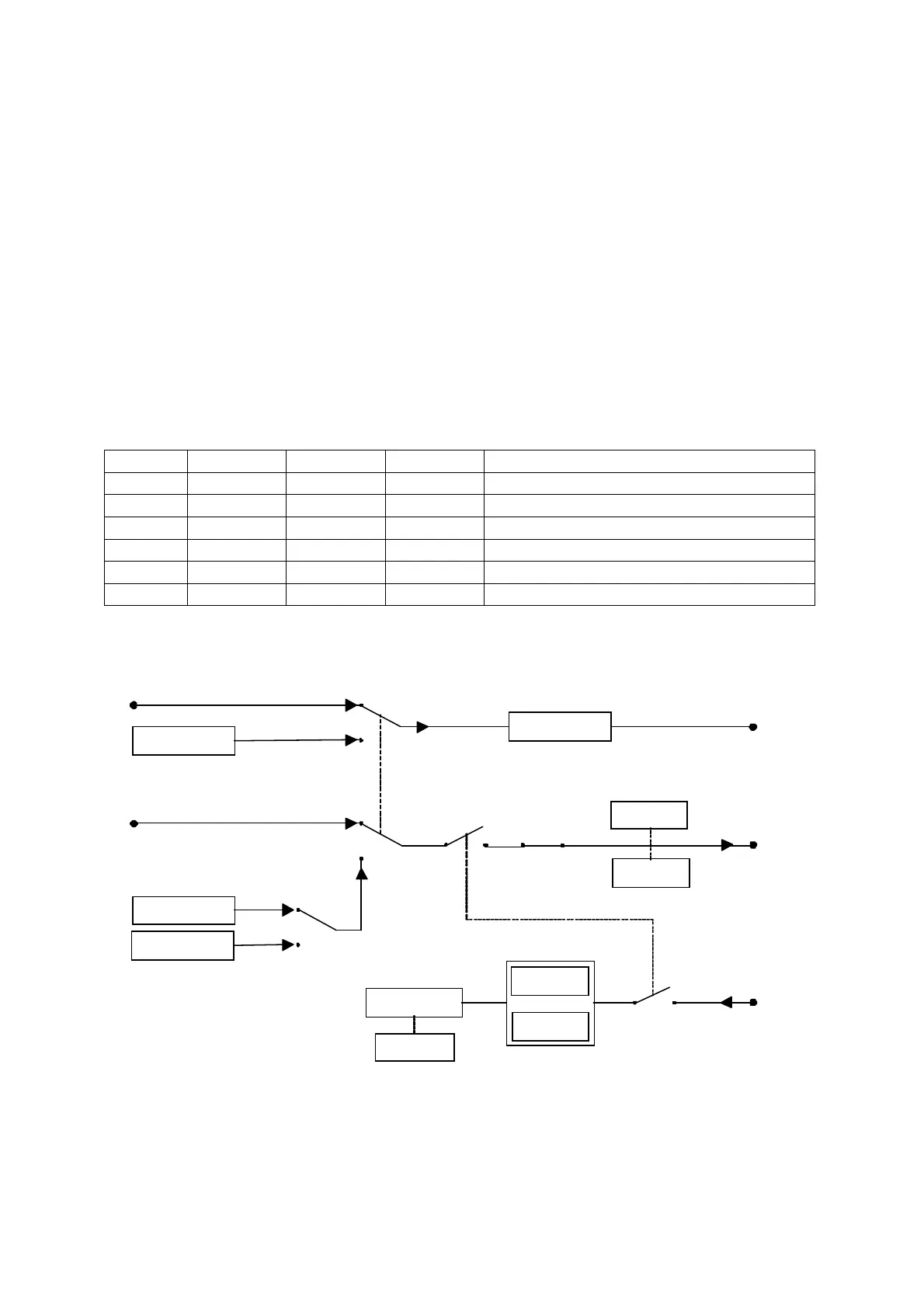
The encoder CAN is active in input and accepts the CAN signal with address setting into
Pr202.
The output encoder CAN is enable if b42.1=0 and it generates a encoder signal with the same
address to CAN node. The CAN node address regarding SBC protocol is the value Pr27+1.
If the address of the input encoder (Pr202) is setting at the same value of the output address
(Pr27+1), the axe which generates the encoder CAN, reads input the encoder CAN output
signal.
If the command b42.0 is enable, is possible to generate a encoder virtual signal. But
differently to encoder traditional, setting b70.10=1 the reference isn’t the speed into Pr3 but is
the position into the parameter pointed from Pr158.
The bit b39.15 is watchdog bit for encoder CAN, and every time that an encoder message
arrives the status is 1.
If the encoder CAN function is activated, the number of the free parameter decrease. See the
next table.
PAR MIN MAX DEF DESCRIPTION
154 -32000 +32000 ratio numerator encoder in CAN
155 -32000 +32000 ratio denominator encoder in CAN
156 -231 231 encoder CAN counter
157 -231 231 encoder CAN counter
158 0 255 pointer for encoder out via CAN
159 -9000 +9000 Encoder CAN speed
Not compatible function with operating OPM15
Pr 3
Pr 3
Pr 158
Pr 44
Pr 48
Pr 27
Pr 154
Pr 155
X 2
( CAN )
Motor position
Motor position
Pr 202
Pr 157 : 156
Virtual speed encoder
Pointer encoder CAN
Input encoder CAN
counter
Address encoder
CAN read
CAN setpoint
multiplicative factor
CAN setpoint
divisor
Pulse numebr per
turn motor
Address encoder
CAN our
CAN baudrate
b 70 . 8
b 40 . 1
b 42 . 0
b 70 . 10
b 70 . 8
Enable message
encoder CAN out
Enable encoder
CAN
Enable ref erence
encoder CAN by
pointer
Enable v irtual axis
X 2
( CAN )
b 42 . 0
I and II axes
encoder OUT
Virtual speed encoder
 Loading...
