Parker Hannifin S.p.A. Divisione S.B.C. user’s manual TWIN-N and SPD-N
137
For pico-PLC writing, it will contain the operating code of the
instruction (see
Serial interface).
Data Address This field is the address of the parameter involved in the operation
(parameter number * 2).
The PLC instructions have the address from 8192 up to 8703.
The electronic cam0 table have the address from 4096 to 4609.
The electronic cam1 table have the address from 4610 to 5123.
The electronic cam2 table have the address from 5124 to 5637.
The electronic cam3 table have the address from 5638 to 6151.
Cmd & Len
Sub-field Value
Meaning
Cmd [0..4] 0
Read request
1
Write
2
SET bit Pr = Pr .OR. Data
3
RESET bit Pr = Pr .AND. (.NOT.Data)
4
TOGGLE bit Pr = Pr .XOR. Data
5 – 31 Not use
Len [5..7] 0- 4
Number of significant bytes in the data field
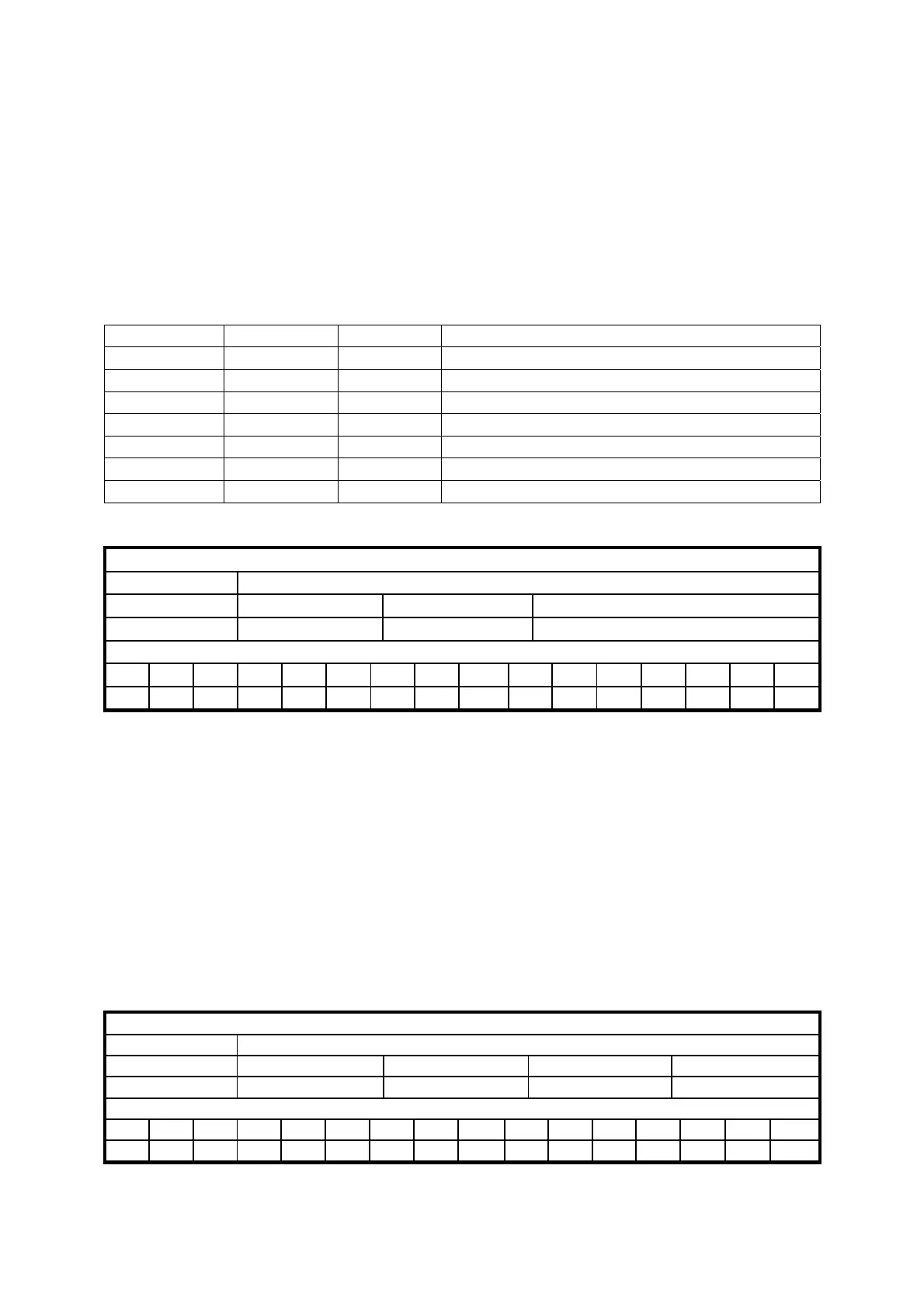
Acyclic response to a parameter request message from drive to master (PDO 2)
Data reply
Data length
8 bytes
Field Name
Addr & Spare Data address Data
Contents
Pr27 16 address 32 bit reply data
Identifier
ID2 ID1 ID0 - - - - - ID10 ID9 ID8 ID7 ID6 ID5 ID4 ID3
A2 A1 A0 X X X X X 0 1 0 1 A6 A5 A4 A3
A0:A6 Drive address (Pr49), valid values 1..127.
PDO3 (tx) object :
This is used to generate a message with the data required to implement a reserved function.
PDO4 (tx/rx) object :
In this case, a parameter exchange function is implemented with the movement related to the
logic functions managed by pico-PLC. In fact, for each transmission of PDO4 rx from the
master to the drive node, the bytes contained in the message are interpreted as follows:
Parameter Pr80..83 write message from master to drive (PDO 4 rx)
Data receive
Data length
8 bytes
Field Name
Pr80 Pr81 Pr82 Pr83
Contents
16 bit value 16 bit value 16 bit value 16 bit value
Identifier
ID2 ID1 ID0 - - - - - ID10 ID9 ID8 ID7 ID6 ID5 ID4 ID3
A2 A1 A0 X X X X X 1 0 1 0 A6 A5 A4 A3
 Loading...
