Parker Hannifin S.p.A. Divisione S.B.C. user’s manual TWIN-N and SPD-N
147
OBJECT DESCRIPTION
INDEX 6040h
Name Controlword
Object Code VAR
Data Type UNSIGNED16
Category Mandatory
ENTRY DESCRIPTION
Access rw
PDO Mapping Possible
Value Range UNSIGNED16
Default Value No
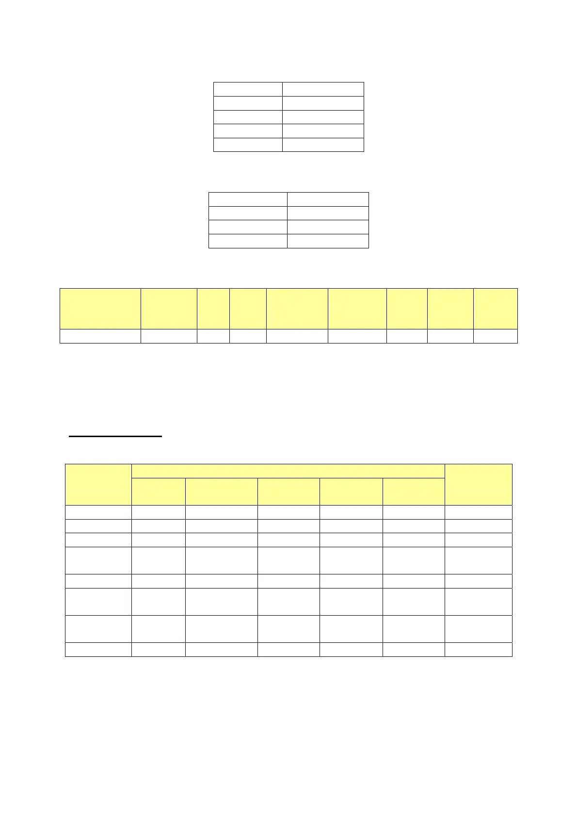
DATA DESCRIPTION The bits of the
controlword are defined as follows:
15 11 10 9 8 7 6 4 3 2 1 0
Manufacturer
specific
Reserved Halt
Fault
reset
Operation
mode
specific
Enable
operation
Quick
stop
Enable
voltage
Switch
on
O O O M O M M M M
MSB LSB
0 -Optional
M –Mandatory
BITS 0 – 3 AND 7:
Device control commands are triggered by the following bit patterns in the controlword:
Bit of the controlword
Command
Fault
reset
Enable
operation
Quick stop
Enable
voltage
Switch on
Transitions
Shutdown 0 X 1 1 0 2,6,8
Switch on 0 0 1 1 1 3*
Switch on 0 1 1 1 1 3**
Disable
voltage
0 X X 0 X 7,9,10,12
Quick stop 0 X 0 1 X 7,10,11
Disable
operation
0 0 1 1 1 5
Enable
operation
0 1 1 1 1 4,16
Fault reset X X X X 15
Table 4: Device control commands
(bits marked X are irrelevant, * ... In the state
SWITCHED ON the drive executes the functionality of this state., ** ... It exists no
functionality in the state SWITCHED ON. The drive does not do any in this state.)
 Loading...
