Parker Hannifin S.p.A. Divisione S.B.C. user’s manual TWIN-N and SPD-N
52
BEFORE BEGINNING
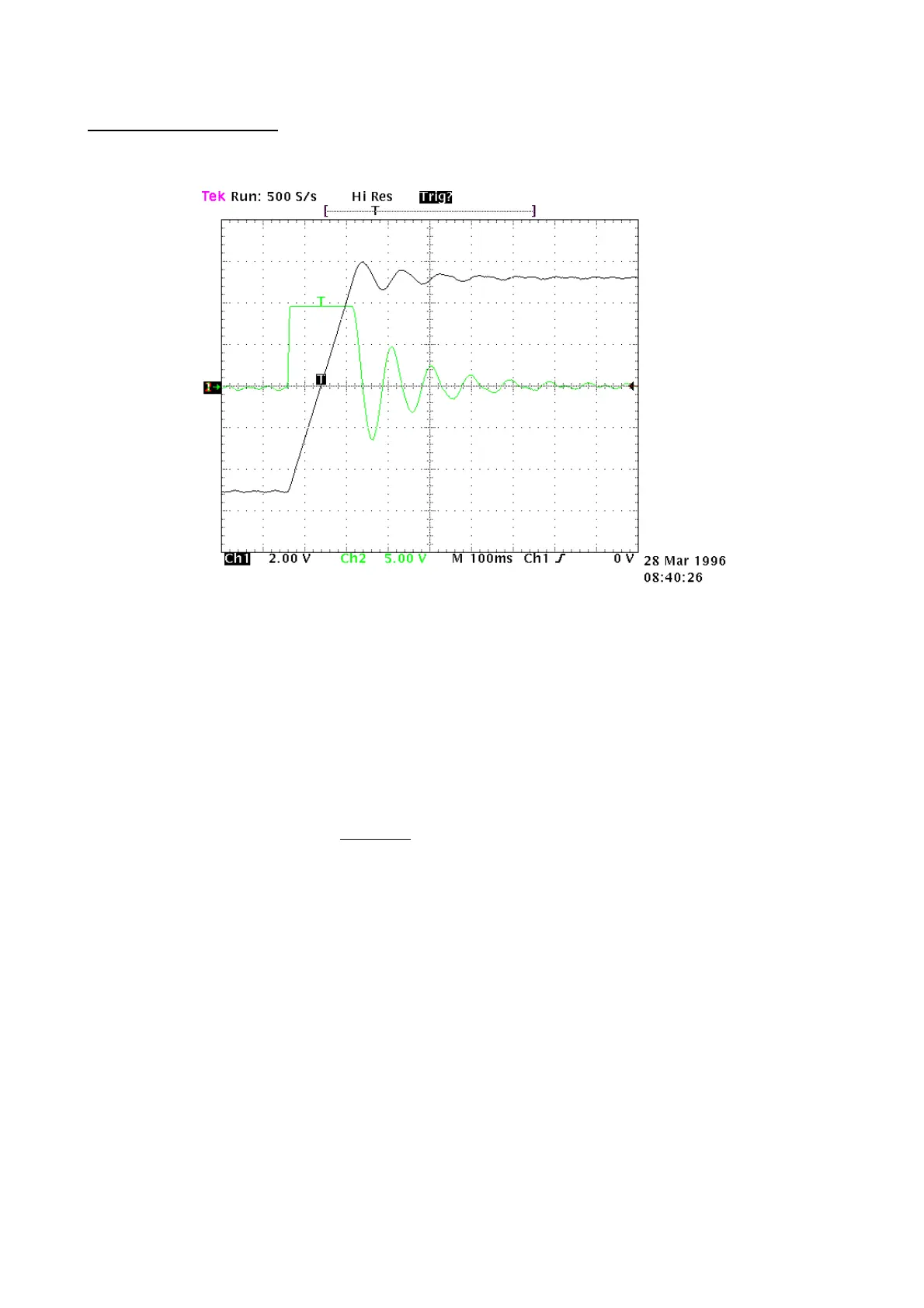
Study the diagram below carefully (Fig. 1):
Fig. 1
This diagram shows the response of the system to a square wave speed reference. Channel 1 (Ch1)
represents the speed and channel 2 (Ch2) the current of the motor. In practice, the probe has been
connected to terminal 6 of the X4 (Vout). The two traces cannot be seen at the same time, but the
trace to be displayed can be programmed using the binary parameter b42.4. The V/div scale and the
time basis will not be discussed here since they can vary greatly.
ESTIMATING THE Pr16
Before turning the converter on, the user should estimate the value of Pr16. The value of Pr16 is what
defines the gain of the system. To convert the value of Pr16 into grades per rated torque, the formula
to be used is the following:
α
=⋅
Pr *
Pr *
33 100
16
28
Ipd
where α represents the stiffness and Ipd is the peak
current of the drive. Before using the formula, Pr33 must be set with the correct value of the rated
current of the motor. To evaluate the correct value of
α, let’s consider that, if the mechanical part to
be moved is rigid (non-elastic) and if there is no transmission play, the optimal stiffness would be
about 4 degrees. If the mechanical part is not rigid enough, it could be necessary to reduce the gain. If
the torque of the motor has been sized in order to obtain strong acceleration, but during the operation,
the disturbing torques are very low, it is possible to choose stiffness angles of 20, 30 or 40 degrees,
thereby maintaining acceptable performance. If it is difficult to choose the proper stiffness angle, the
user can begin with 10 degrees that is the default adjustment if a motor with the same rated current as
the converter’s is used.
At this point, let us set the Pr16 to the estimate and turn on the axis with a square wave reference.
The user must be careful to choose reference ranges and frequencies in order to avoid problems if the
axis has a limited course. By observing the oscilloscope we will note that as Pr17 varies, the response
will change. For decreasing values of Pr17, the response of the system will be as shown in figure 2
below:
 Loading...
