Parker Hannifin S.p.A. Divisione S.B.C. user’s manual TWIN-N and SPD-N
81
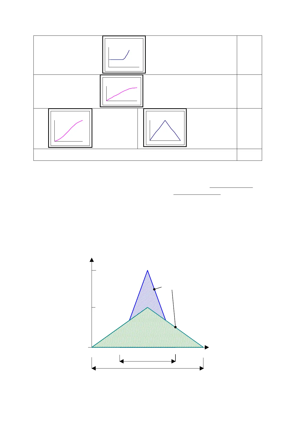
rampa aggancio
Engage ramp
Tab1
rampa sgancio
Disengage ramp
Tab2
y=x-senx
function y=x-senx
profilo triangolare
Triangular profile of speed
Tab3
Pr102=14
Adaptation module of CAM1 through Pr176:177 and Pr178:179
CAM1
Pr102 can be setting through serial line, CAN or pico-PLC internal to the drive. It’s not
possible set this parameter using the display.
The activation of the table in the cam generator, can be given by direct command
that
executes immediately the selected table, or defining one phase of the master
and determining
the activation point. It is to cure of the customer the synchronization of the functions during
the passages between the tables.
As a OPM14 default configuration, the CAM1 is scanned through the master module, using
Adaptation module command (Pr102=14) the function is scanned in one sector of master
module. The selected cam can be scaled in a sector of the master module by programming the
starting point Pr177:176 and the space Pr179:178 in which the cam shall be executed.
The parameter values “starting point” and “space” must be included between 0 and master
module in Pr111:110.
Master module
[count]
100000
3000rpm
2500 75005000
Speed axis slave
[rpm]
1500rpm
(Motor speed limit)
Slave module
Pr115:114
Pr102=9
Pr102=11
Pr102=12
Pr102=10
 Loading...
