Parker Hannifin S.p.A Divisione S.B.C. user’s manual TWIN-N and SPD-N
92
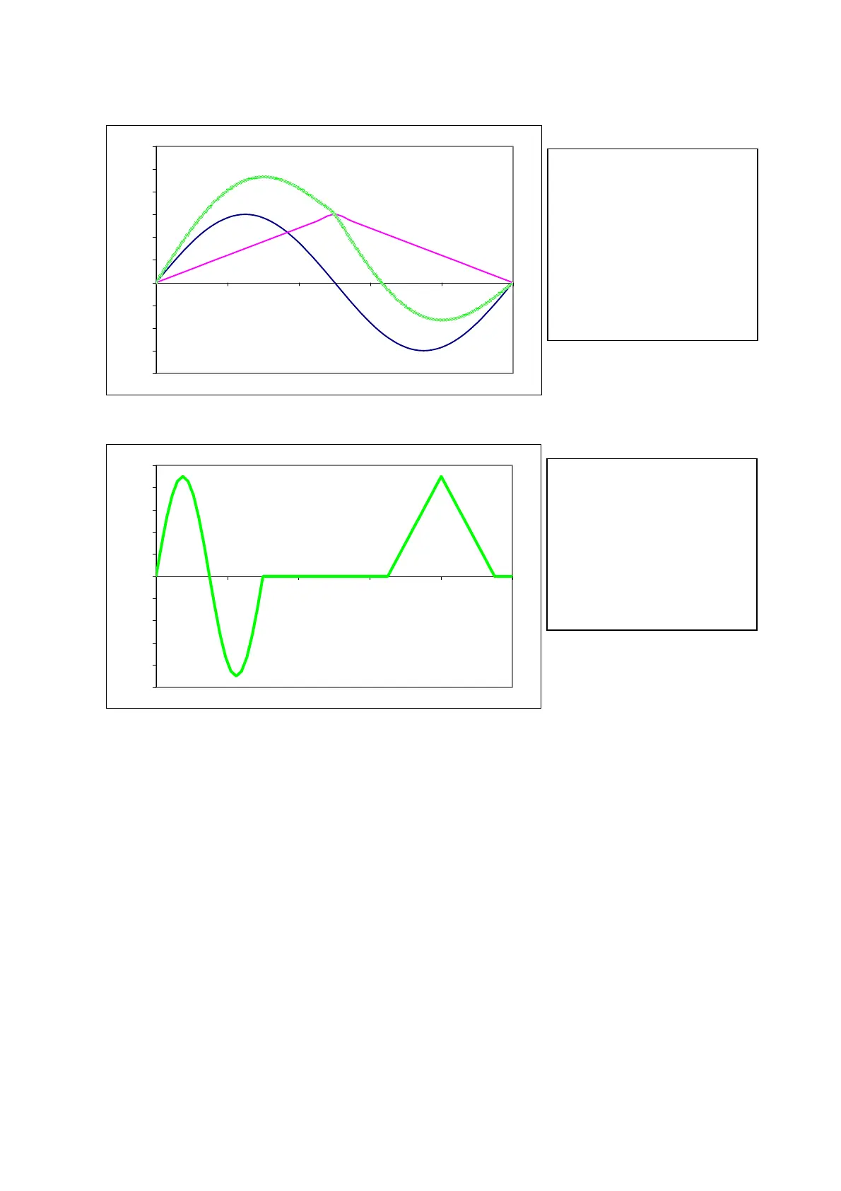
Example 1
-2000
-1500
-1000
-500
0
500
1000
1500
2000
2500
3000
0 2000 4000 6000 8000 10000
Example 2
-5000
-4000
-3000
-2000
-1000
0
1000
2000
3000
4000
5000
0 2000 4000 6000 8000 10000
After the default of operating mode, the CAM2 generator operates on table 3, but through the
management of bit b182.6 and b181,7, is possible to change the reference table.
The reference of position given from the algebraic sum of the three generators, pass through a
ratio block that, Pr182 and Pr183, before being transmitted to the loop of position.
CAM1
CAM2
Profilo risultante
Master module]
Speed profile axis slave without cam scale
Speed [rpm]
S
eed
rofile axis slave with cam scale
CAM1
CAM2
Speed [rpm]
Master module [count]
Scale CAM1:
Pr115:114=10000 module
Pr177:176=6500 start point
Pr179:178=9500 execution space
Pr102=14 calculation scale command
Scale CAM2:
Pr185:184=10000 module
Pr177:176=0 start point
Pr179:178=3000 execution space
Pr102=13 calculation scale command
Scale CAM1:
Pr115:114=10000 module
Pr177:176=00 start point
Pr179:178=10000 execution space
Scale CAM2:
Pr185:184=10000 module
Pr177:176=0 start point
Pr179:178=10000 execution space
Scale status of the OPM11 default of
cam
 Loading...
