SECTION V
DETAILED ELECTRICAL AND LOGIC DESCRIPTION
5.1
INTRODUCTION
This section contains the theory
of
operation
of
the PCBAs used
in
the 03000 Disk Drive.
Schematic and assembly drawings for each board are contained at the end
of
Section VII.
5.2 LOGIC TERM
MNEMONIC
IDENTIFICATION
All digital signals in the 03000 Disk Drive are identified by a name which will
be
referred to
as
the logic term.
Logic terms may
be
descriptive
of
a condition or
an
event,
or
they may
be
a generalized
name used primarily for documentation purposes.
If
a descriptive name is essential to
facilitate the understanding
of
a function, a generalized term is not used.
Appendix A of this manual contains the mnemonic listing for the standard
03000 Series
Disk Drive.
An
understanding
of
the mnemonic scheme employed is essential to the total
understanding
of
the 03000 logic drawings. Also included in Appendix A are figures
and
tables which provide the user with
an
understanding of the six character logic term.
5.3
SERVO PCBA
The
following paragraphs describe the Servo PCBA installed in the 03000 Series Disk
Drive. Refer to
Schematic No.
102810
and Assembly No. 102811.
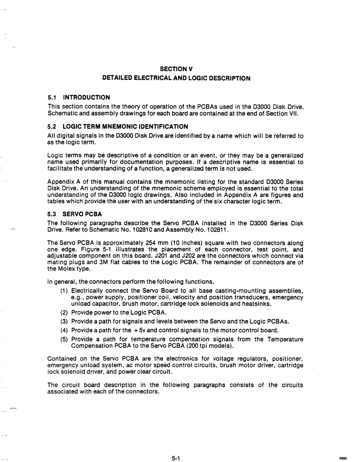
The Servo
PCBA
is approximately
254
mm
(10
inches) square with two connectors along
one edge. Figure
5-1
illustrates the placement of each connector, test pOint,
and
adjustable component
on
this board.
J201
and J202 are the connectors which connect via
mating
plugs and
3M
flat cables to the Logic PCBA. The remainder
of
connectors
are
of
the Molex type. .
In
general, the connectors perform the following functions.
(1)
Electrically connect the Servo Board to all base casting-mounting assemblies,
e.g., power supply, positioner coil, velocity and position transducers, emergency
unload capacitor, brush motor, cartridge lock solenoids and heatsinks.
(2)
Provide power to the Logic PCBA.
(3)
Provide a path for signals and levels between the Servo and the Logic PCBAs.
(4)
Provide a path for the +
5v
and control Signals
to
the motor control board.
(5)
Provide a path for temperature compensation signals from the Temperature
Compensation
PCBA
to the Servo
PCBA
(200
tpi models).
Contained
on
the Servo PCBA are the electronics for voltage regulators, positioner,
emergency unload system, ac motor speed control circuits, brush motor driver, cartridge
lock solenoid driver, and power clear circuit.
The
circuit board description in the following paragraphs consists of the circuits
associated with
each
of
the connectors.
5-1
6300