6300
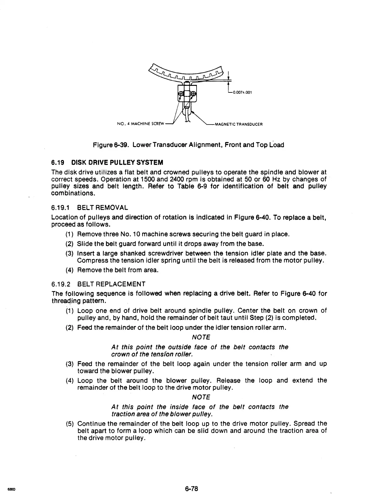
Figure 6-39. Lower Transducer Alignment, Front and Top Load
6.19 DISK DRIVE PULLEY SYSTEM
The
disk drive utilizes a flat belt and crowned pulleys to operate the spindle
and
blower at
correct speeds. Operation at
1500
and
2400
rpm is obtained at
50
or
60
Hz
by
changes of
pulley sizes and belt length. Refer to Table 6-9 for identification of belt
and
pulley
combinations.
6.19.1
BELT REMOVAL
Location of pulleys and direction
of
rotation is indicated
In
Figure 6-40.
To
replace a belt,
proceed
as
follows.
(1)
Remove
three No.1 0 machine screws securing the belt guard in place.
(2)
Slide the belt guard forward until it drops
away
from the base.
(3)
Insert a large shanked screwdriver between the tension idler plate and the base.
Compress the tension idler spring until the belt is released from the motor
pulley.
(4)
Remove
the belt from
area.
6.19.2 BELT REPLACEMENT
The
following sequence is followed when replacing a drive belt. Refer to Figure
6-40
for
threaqing pattern.
(1)
Loop one end of drive belt around spindle pulley. Center the belt
on
crown of
pulley and, by hand, hold the remainder
of
belt taut until Step
(2)
is completed.
(2)
Feed
the remainder
of
the belt loop under the idler tension roller arm.
NOTE
At
this
point
the outside face
of
the belt contacts the
crown
of
the tensfon rol/er.
(3)
Feed
the remainder of the belt loop again under the tension roller
arm
and
up
toward the blower pulley.
(4)
Loop the belt around the blower pulley. Release the loop and extend the
remainder of the
belt loop to the drive motor pulley.
NOTE
At
this
point
the inside face
of
the
belt
contacts the
traction area
of
the blower pul/ey.
(5)
Continue the remainder of the belt loop
up
to the drive motor pulley.
Spread
the
belt apart to form a loop which
can
be
slid down
and
around the traction
area
of
the drive motor pulley.
6-78