(8)
Adjust the closure pOint, if required, by loosening the
No.2
machine screws
securing the switch in place and sliding the switch body
vertically until the
previously established requirements are met. Remove the
tool.
(9)
Reinstall
P109
onto the Logic PCBA.
(10)
Return the Logic PCBA to the normal position.
(11)
Reinstall the dust cover and return the disk drive to the enclosure.
6.17
BEZEL AND POWER SWITCH
6.17.1 REMOVAL OF BEZEL
Removal or adjustment of the bezel is made by loosening three socket-head countersunk
Allen machine screws securing the assembly to the base assembly.
NOTE
The
holes through which the screws pass
are
slotted to
allow for bezel removal without removing screws.
To
remove the bezel, proceed
as
follows.
(1)
Back-off the six machine screws enough to clear the bezel supports on each side
of the bezel.
(2)
Pull the assembly forward and away from the deck assembly.
(3)
Access to parts requiring replacement
or
adjustment is now available.
6.17.2
INSTALLATION OF BEZEL
To
install the bezel, proceed
as
follows.
(1)
Ensure that the six machine screws are backed-off enough
to
clear the bezel
support on
each
side of the bezel.
(2)
Carefully position the bezel to the deck assembly and secure the bezel mounting
screws.
6.17.3
REMOVAL OF
POWER
SWITCH BRACKET
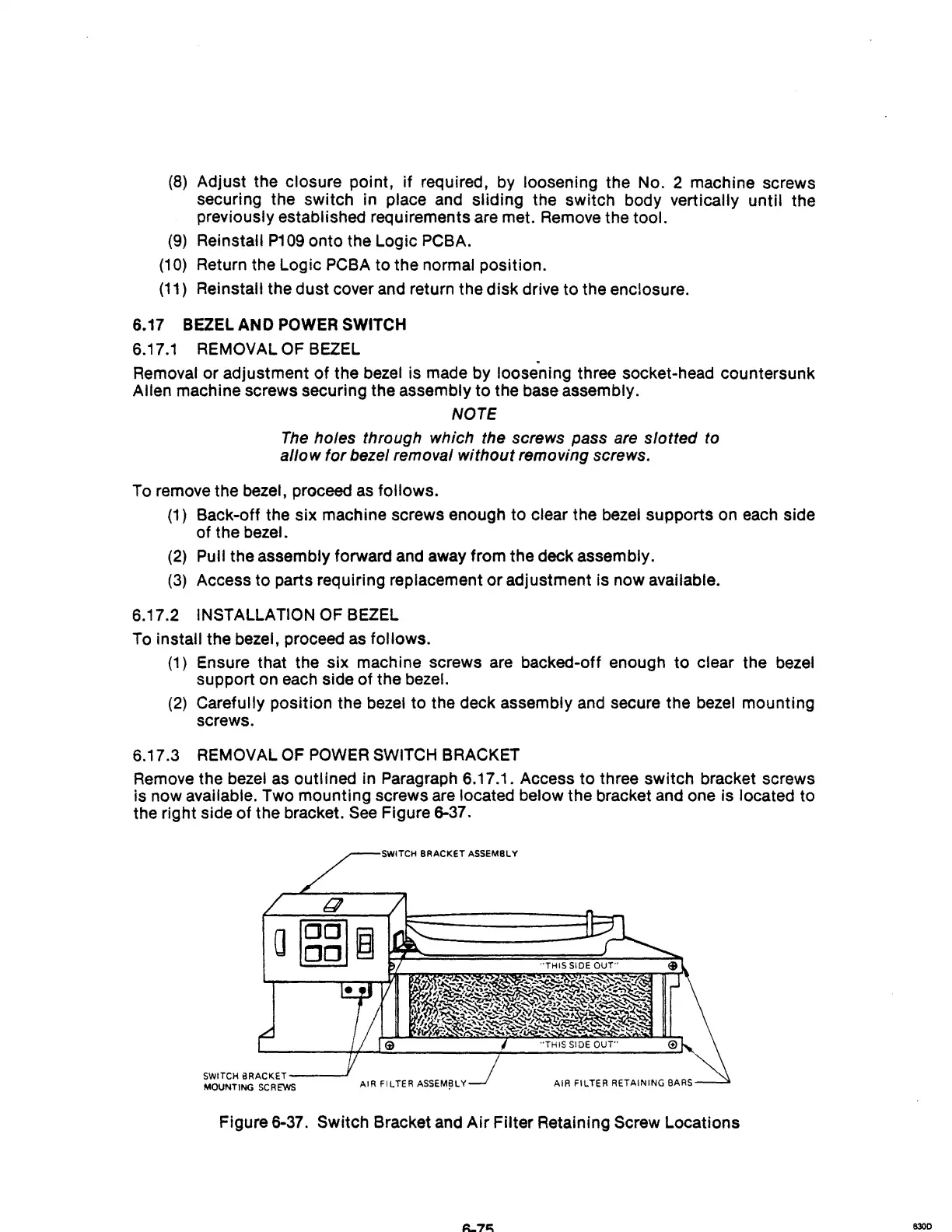
Remove the bezel
as
outl ined in Paragraph 6.17.1. Access
to
three switch bracket screws
is now available. Two mounting screws are located below the bracket and one is located to
the right side of the bracket.
See
Figure 6-37 .
.,..--s;wm:H
BRACKET ASSEMBLY
SWITCH
BRACKET---..J
MOUNTING
SCREWS
AIR FILTER
ASSEM~LY
AIR FILTER RETAINING BARS
Figure 6-37. Switch Bracket and
Air
Filter Retaining Screw Locations
8300