6.5 PART REPLACEMENT ADJUSTMENTS
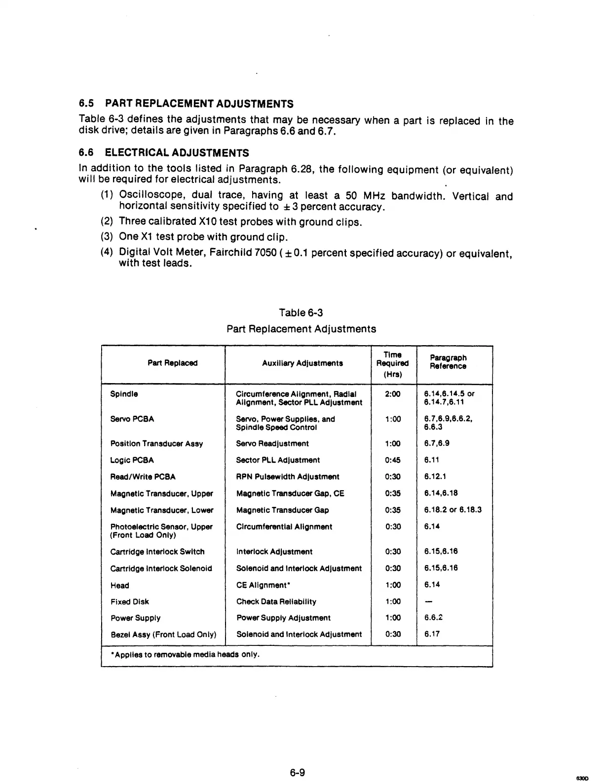
Table 6-3 defines the adjustments that may
be
necessary when a part is replaced in the
disk drive; details are given in Paragraphs 6.6 and 6.7.
6.6 ELECTRICAL ADJUSTMENTS
In
addition to the tools listed in Paragraph 6.28, the following equipment (or equivalent)
will
be
required for electrical adjustments.
(1)
Oscilloscope, dual trace, having at least a
50
MHz bandwidth. Vertical and
horizontal sensitivity specified to
± 3 percent accuracy.
(2)
Three calibrated
X10
test probes with ground clips.
(3)
One
X1
test probe with ground clip.
(4)
Digital Volt Meter, Fairchild
7050
( ±
0.1
percent specified accuracy) or equivalent,
with test leads.
Table 6-3
Part Replacement Adjustments
Time
Paragraph
Part Replaced
Auxiliary Adjustments Required
Reference
(Hrs)
Spindle
Circumference Alignment, Radial 2:00
6.14,6.14.5 or
Alignment, Sector PLL Adjustment
6.14.7,6.11
Servo PCBA Servo, Power
Supplies, and 1:00
6.7,6.9,6.6.2,
Spindle Speed Control
6.6.3
Position Transducer Assy Servo Readjustment 1:00
6.7,6.9
LogicPCBA
Sector PLL Adjustment
0:45
6.11
Read/Write PCBA
RPN
Pulsewldth Adjustment 0:30
6.12.1
Magnetic Transducer, Upper
Magnetic Transducer Gap,
CE
0:35
6.14,6.18
Magnetic Transducer, Lower Magnetic Transducer Gap
0:35
6.18.2 or 6.18.3
Photoelectric Sensor, Upper Circumferential Alignment 0:30
6.14
(Front Load Only)
Cartridge Interlock Switch
Interlock
Adjustment 0:30
6.15,6.16
Cartridge Interlock Solenoid Solenoid and Interlock Adjustment 0:30
6.15,6.16
Head
CE
Alignment'
1:00
6.14
Fixed Disk
Check Data Reliability 1:00
-
Power Supply Power Supply Adjustment
1:00
6.6.2
Bezel Assy (Front Load
Only)
Solenoid and Interlock Adjustment 0:30
6.17
• Applies
to
removable media heads only.
6-9