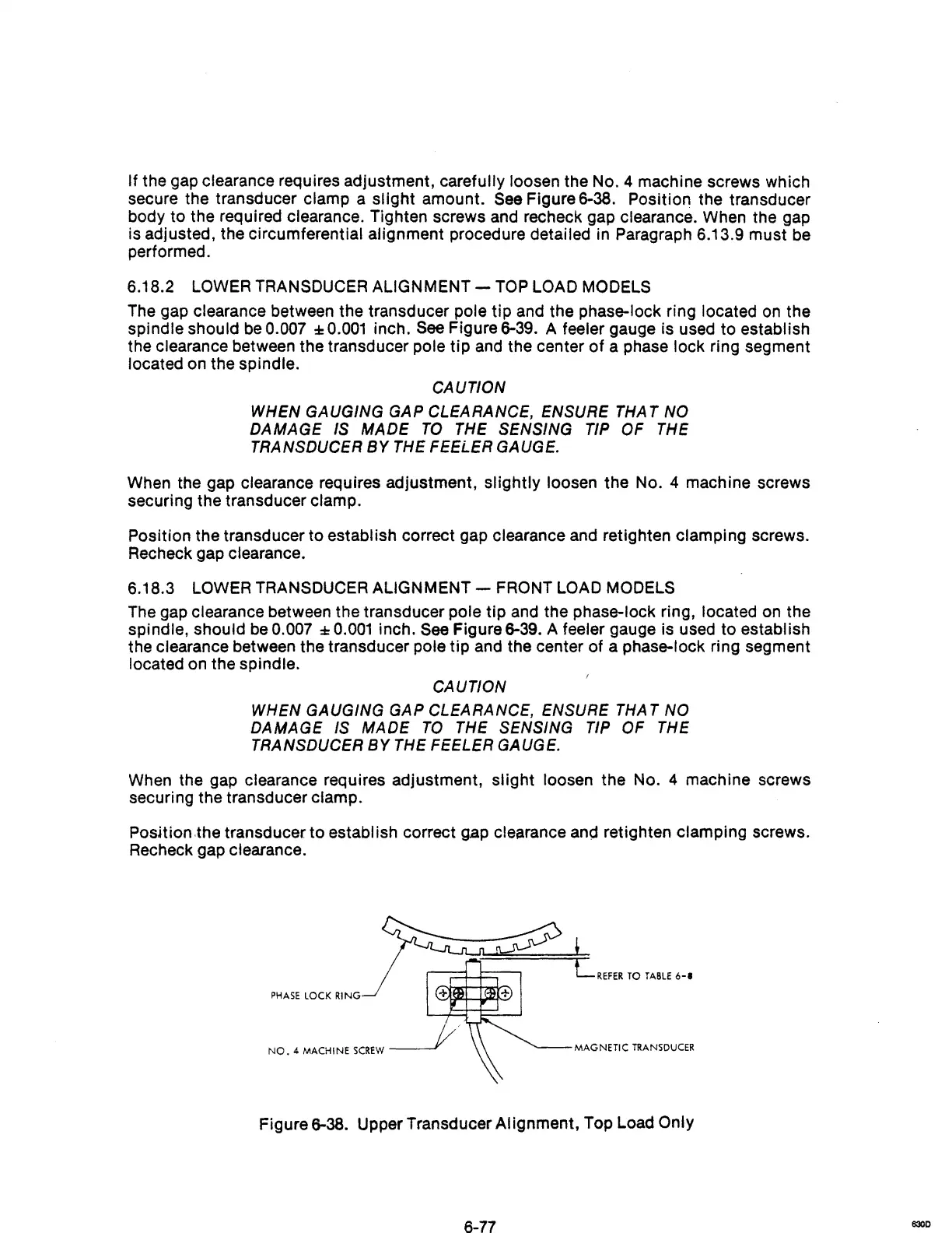
If the gap clearance requires adjustment, carefully loosen the
No.4
machine screws which
secure the transducer clamp a slight amount.
See
Figure 6-38. Position the transducer
body to the required clearance. Tighten screws and recheck gap clearance. When the gap
is adjusted, the circumferential alignment procedure detailed in Paragraph 6.13.9 must
be
performed.
6.18.2
LOWER
TRANSDUCER ALIGNMENT -
TOP
LOAD MODELS
The
gap clearance between the transducer pole
tip
and the phase-lock ring located
on
the
spindle should
be
0.007 :
0.001
inch.
See
Figure 6-39. A feeler gauge is used to establish
the clearance between the transducer pole
tip
and
the center
of
a phase lock ring segment
located on the spindle.
CAUTION
WHEN GAUGING GAP CLEARANCE, ENSURE THAT NO
DAMAGE
IS
MADE
TO
THE SENSING TIP
OF
THE
TRANSDUCER
BY
THE FEELER GAUGE.
When the gap clearance requires adjustment, slightly loosen the
No.4
machine screws
securing the transducer clamp.
Position the transducer to establish correct gap clearance and retighten clamping screws.
Recheck gap clearance.
6.18.3
LOWER
TRANSDUCER ALIGNMENT - FRONT LOAD MODELS
The
gap clearance between the transducer pole tip
and
the phase-lock ring, located on the
spindle, should
be
0.007
:0.001
inch. See Figure 6-39. A feeler gauge is used to establish
the clearance between the transducer pole tip and the center of a phase-lock ring segment
located
on
the spindle.
CAUTION
WHEN GAUGING
GAP
CLEARANCE, ENSURE
THAT
NO
DAMAGE
IS
MADE
TO
THE SENSING TIP OF THE
TRANSDUCER
BY
THE FEELER GAUGE.
When the gap clearance requires adjustment, slight loosen the
No.4
machine screws
securing the transducer clamp.
Position ,the transducer to establish correct gap clearance
anej
retighten clamping screws.
Recheck gap clearance.
LREFER
TO
TABLE
6-1
NO.4
MACHINE
SCREW
_-----J
MAGNETIC
TRANSDUCER
Figure 6-38. Upper Transducer Alignment, Top Load Only
6-77
830D