Figure 6-10. Current Waveform After Adjustment
of
R111
REVERSE
STROKE--;'I
-
FORWARD
STROKE~
SEEK
TIME
SEEK
TIME
35
MSEC
(38
MSEC
200
TPI)*
35
MSEC
(38
MSEC
200
TPI)*
"AVERAGE
TIME
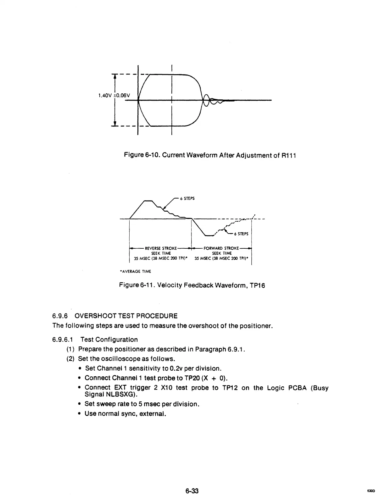
Figure 6-11. Velocity Feedback Waveform,
TP16
6.9.6 OVERSHOOT TEST PROCEDURE
The following steps are used
to
measure the overshoot
of
the positioner.
6.9.6.1
(1
)
(2)
Test Configuration
Prepare the positioner
as
described in Paragraph 6.9.1.
Set the oscilloscope as follows.
• Set Channel 1 sensitivity to 0.2v per division.
• Connect Channel 1 test probe to
TP20
(X
+ 0).
•
Connect
EXT
trigger 2
X10
test probe
to
TP12
on the Logic PCBA (Busy
Signal NLBSXG).
• Set sweep rate
to
5 msec per division.
• Use normal sync, external.
6300