SECTION VI
MAINTENANCE AND TROUBLESHOOTING
6.1
INTRODUCTION
This section provides information necessary to perform electrical and mechanical
adjustments, parts replacement, and troubleshooting. Sections
IV
and V contain the
theory of operation of components and circuits
for
reference.
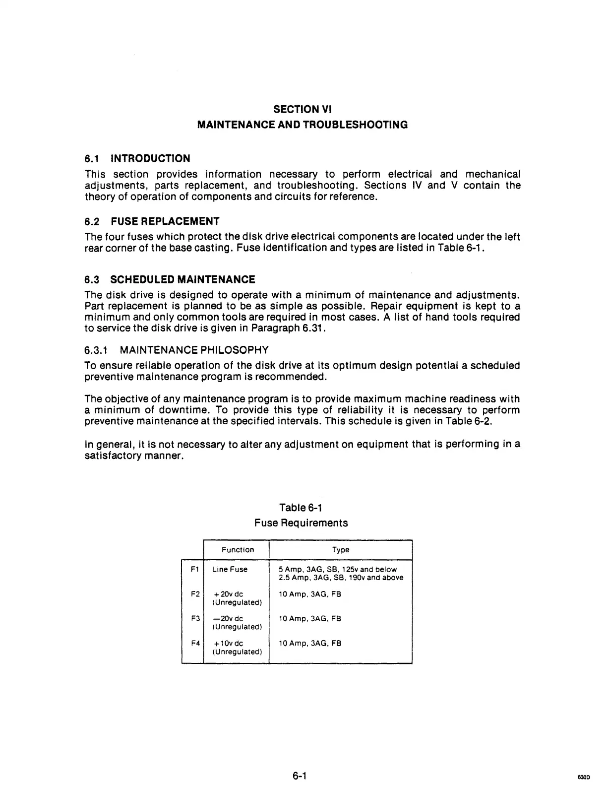
6.2 FUSE REPLACEMENT
The four fuses which protect the disk drive electrical components
are
located under the left
rear corner of the base casting. Fuse identification and types are listed in Table 6-1.
6.3
SCHEDULED MAINTENANCE
The
disk drive is designed
to
operate with a minimum
of
maintenance and adjustments.
Part replacement is planned to
be
as
simple as possible. Repair equipment is kept to a
minimum and only common tools are required in most cases.
A
list
of hand tools required
to
service the disk drive is given in Paragraph 6.31.
6.3.1
MAINTENANCE PHILOSOPHY
To
ensure reliable operation
of
the disk drive at its optimum design potential a scheduled
preventive maintenance program is recommended.
The
objective
of
any maintenance program is to provide maximum machine readiness with
a minimum
of
downtime.
To
provide this type of reliability
it
is necessary
to
perform
preventive maintenance at the specified intervals. This schedule is given in Table 6-2.
In
general,
it
is not necessary
to
alter any adjustment on equipment that is performing in a
satisfactory manner.
Table
6-1
Fuse Requirements
Function
Type
F1
Line Fuse 5 Amp. 3AG. SB. 125v and below
2.5 Amp. 3AG.
SB. 190v and above
F2
+
20v
dc 10 Amp. 3AG. FB
(Unregulated)
F3
-20vdc
10 Amp. 3AG. FB
(Unregulated)
F4
+10vdc
10 Amp, 3AG, FB
(Unregulated)
6-1
630D