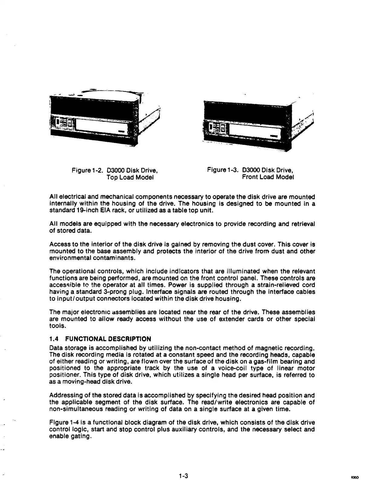
Figure 1-2. 03000 Disk Drive,
Top Load Model
Figure 1-3.
03000 Disk Drive,
Front Load Model
All
electrical and mechanical components necessary
to
operate
the
disk
drive are mounted
Internally
within
the housing
of
the
drive. The housing
is
designed
to
be mounted in a
standard 1 g..inch
EIA rack, or utilized
as
a table top unit.
All
models are equipped
with
the necessary electronics
to
provide recording and retrieval
of
stored data.
Access
to
the interior
of
the
disk
drive
Is
gained by removing the
dust
cover. This cover is
mounted
to
the base assembly and protects the interior
of
the
drive
from
dust and other
environmental contam; nants.
The operational controls, which include indicators that are illuminated when the relevant
functions are being performed, are mounted on the front control
panel. These controls are
acces~ible
t('l the operator at all times. Power is supplied through a strain·relieved cord
having a standard
3--prong plug. Interface signals are routed through the interface cables
to
input/output
connectors located
within
the
disk
drive housing.
The major electronic
assemblies are located near the rear
of
the
drive. These assemblies
are mounted to
allow
ready access
without
the use
of
extender cards or other special
tools.
1.4
FUNCTIONAL DESCRIPTION
Data storage is accomplished by utilizing the non-contact method
of
magnetic recording.
The disk recording media is rotated at a constant speed and the recording heads, capable
of
either reading or writing, are flown over the surface
of
the
disk
on a gas-film bearing and
positioned
to
the appropriate track by the use of a voice-coil type
of
linear
motor
positioner. This type
of
disk
drive, which utilizes a single head per surface, is referred to
as a moving-head
disk
drive.
Addressing
of
the stored data is accompl ished by specifying the desired head position and
the applicable segment
of
the
disk
surface. The read/write electroniCS are capable
of
non·simultaneous reading
or
writing
of
data on a single surface at a given time.
Figure
1-4 is a functional block diagram
of
the
disk
drive, which
consists
of
the
disk
drive
control logic, start and stop control plus auxiliary controls, and the necessary select and
enable gating.
1-3