The
output of
U122-1
(zone 012) is applied to the Lower Electronic Sector Programming
array for purposes of determinng the value loaded into the Sector Countdown Counter.
As previously discussed, the output of
U122,
pin 4 (zone 010) is the raw sector pulse
which is utilized by the Sector Number Counter, Count Control, and the Sector Pulse
Former.
5.6
MOTOR
CONTROL
PCBA
The following paragraphs describe the Motor Control PCBA installed
in
the 03000 Series
Disk Drives. Refer to Schematic No.1
03570
and Assembly No.1
03571.
The Motor Control PCBA is approximately 101.6 mm
(4
inches) square and is physically
located on top of the power transformer. This PCBA is one
of
the subassemblies which
comprise the Power
Supply Chassis. The circuitry contained on the Motor Control PCBA
performs a ground isolation function and provides the drive current necessary for
controlling a triac, which, in turn, switches power
to
the
disk
drive motor. This PCBA is
one of the functional elements in the spindle speed control.
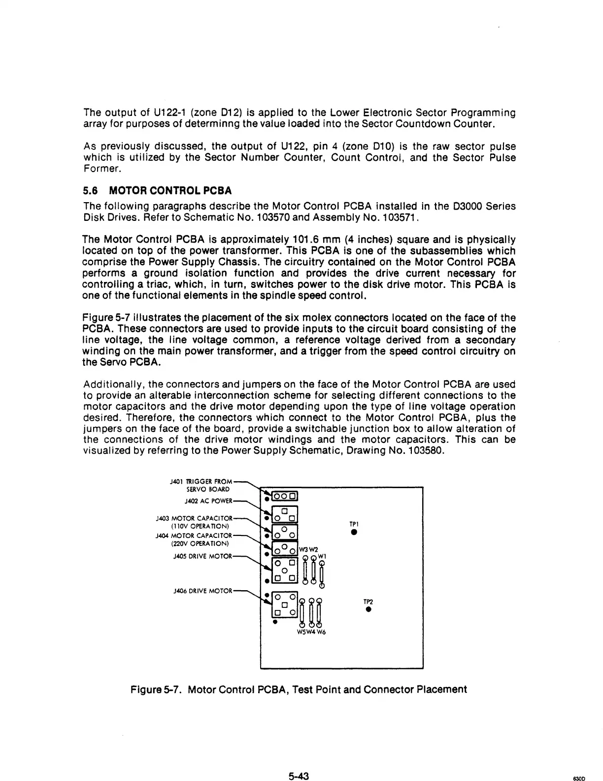
Figure
5-7
illustrates the placement
of
the six molex connectors located on the face
of
the
PCBA. These connectors are used to provide inputs to the circuit board consisting of the
line
VOltage,
the line voltage common, a reference voltage derived from a secondary
winding on the main power transformer, and a trigger from the speed control circuitry on
the
Servo PCBA.
Additionally, the connectors and jumpers on the face of the Motor Control PCBA are used
to provide
an
alterable interconnection scheme for selecting different connections to the
motor capacitors and the drive motor depending upon the type of line voltage operation
desired. Therefore, the connectors which connect to the Motor Control PCBA, plus the
jumpers
on
the face of the board, provide a switchable junction box to allow alteration of
the connections of the drive motor windings and the motor capacitors. This can
be
visualized by referring to the Power Supply Schematic, Drawing No.1
03580.
J401
llUGGER
FROM
SERVO
BOARD
J402
AC
POWER
J403
MOTOR
CAPACITOR
(110V
OPERA
nON)
J404
MOTOR
CAPACITOR
(220V
OPERATION)
J405
DRIVE
MOTOR
J406
DRIVE
MOTOR
TPI
•
TP2
•
Figure 5-7. Motor Control PCBA, Test Point and Connector Placement
5-43
830D