6300
6.9.4.2 Test Procedure
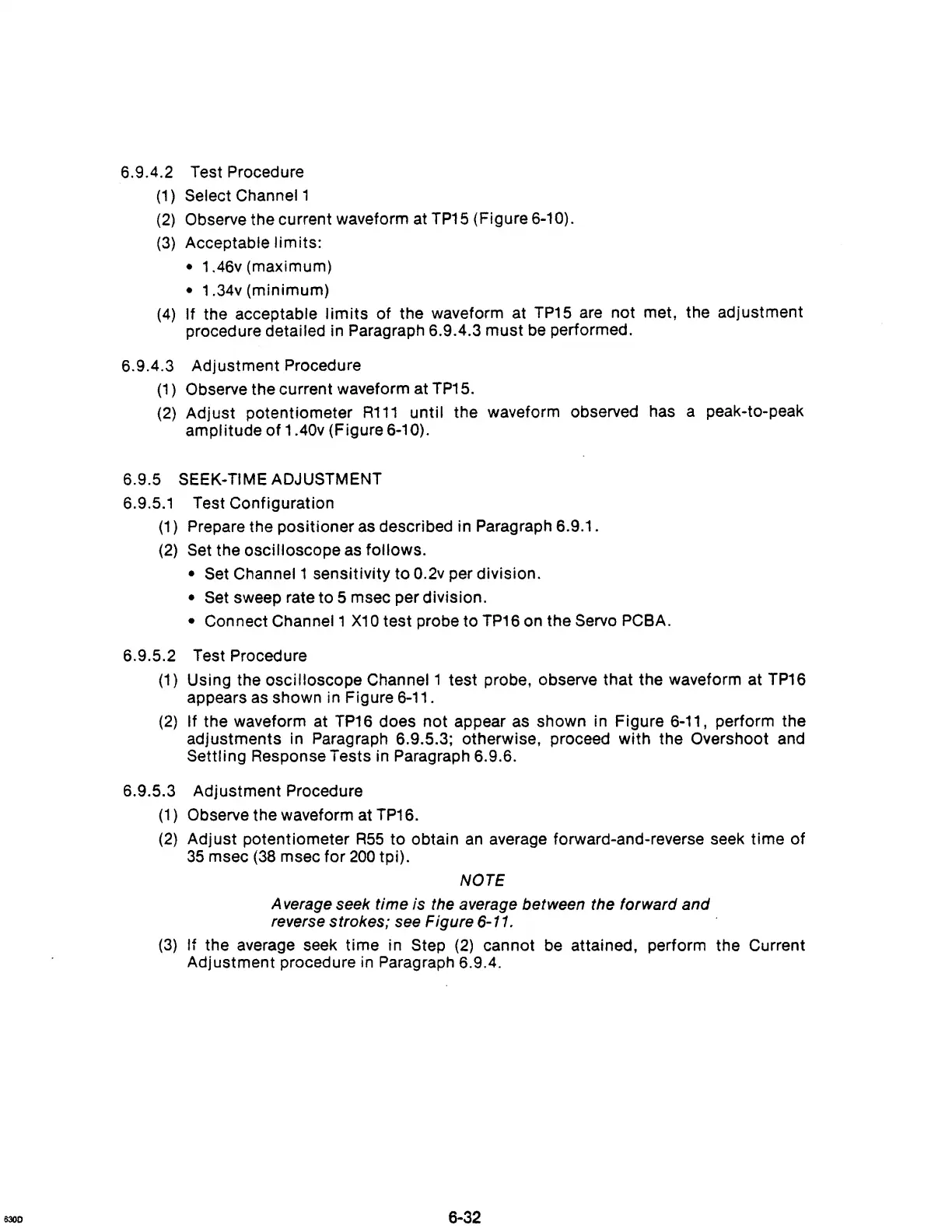
(1)
Select Channel 1
(2)
Observe the current waveform at
TP15
(Figure 6-10).
(3)
Acceptable limits:
• 1 .46v (maximum)
• 1 .34v (minimum)
(4)
If the acceptable
limits
of the waveform at
TP15
are not met, the adjustment
procedure detailed in Paragraph 6.9.4.3 must
be
performed.
6.9.4.3 Adjustment Procedure
(1)
Observe the current waveform at
TP15.
(2)
Adjust potentiometer
R111
until the waveform observed has a peak-to-peak
amplitude
of
1.40v (Figure 6-10).
6.9.5 SEEK-TIME ADJUSTMENT
6.9.5.1 Test Configuration
(1)
Prepare the positioner
as
described in Paragraph 6.9.1.
(2)
Set
the oscilloscope as follows.
•
Set
Channel 1 sensitivity to 0.2v per division.
•
Set
sweep rate to 5 msec per division.
• Connect Channel 1
X10
test probe to
TP16
on the Servo PCBA.
6.9.5.2 Test Procedure
(1)
Using the oscilloscope Channel 1 test probe, observe that the waveform at
TP16
appears
as
shown in Figure 6-11.
(2)
If the waveform at
TP16
does not appear as shown in Figure 6-11, perform the
adjustments in Paragraph 6.9.5.3; otherwise, proceed with the Overshoot
and
Settling Response Tests in Paragraph 6.9.6.
6.9.5.3 Adjustment Procedure
(1)
Observe the waveform at
TP16.
(2)
Adjust potentiometer
R55
to obtain
an
average forward-and-reverse seek time of
35
msec
(38
msec for
200
tpi).
NOTE
A verage seek
time
is
the average between the
forward
and
reverse
strokes;
see Figure 6-11.
(3)
If the average seek time in Step
(2)
cannot
be
attained, perform the Current
Adjustment procedure in Paragraph 6.9.4.
6-32