630D
(10)
One
X1
probe is required
for
single-ended measurement method; two
X1
probes
are required for differential measurement method.
(11)
Front load disk drive
CE
alignment procedures are outlined in Paragraphs 6.14.5
and
6.14.6; top load
disk
drive
CE
alignment procedures are outlined in Paragraphs
6.14.7 and
6.14.8.
6.14.5 RADIAL ALIGNMENT - FRONT LOAD
6.14.5.1
Test Procedure
(100
and
200
tpi)
The test configuration detailed
in
Paragraph 6.14.4 must
be
performed prior to performing
this procedure.
(1)
Set up oscilloscope
as
follows.
•
Connect oscilloscope vertical input to
TP19
on
the Read/Write PCBA; use
TP18
for
ground reference.
• Set vertical sensitivity to 0.1v
(50
mv
for
200
tpi) per division and select the
ac input mode.
• Connect
an
X10
test probe from the external trigger input
of
the oscilloscope
t9
TP2
(Index)
on
the Logic PCBA.
• Use external trigger and normal sync,
ac
coupled,
on
the negative trigger slope.
• Set sweep rate to 5 msec per division.
(2)
Set exerciser to position the heads
to
cyl inder 1
00
(200
for
200
tpi).
(3)
Select head 0 (upper surface
of
upper disk).
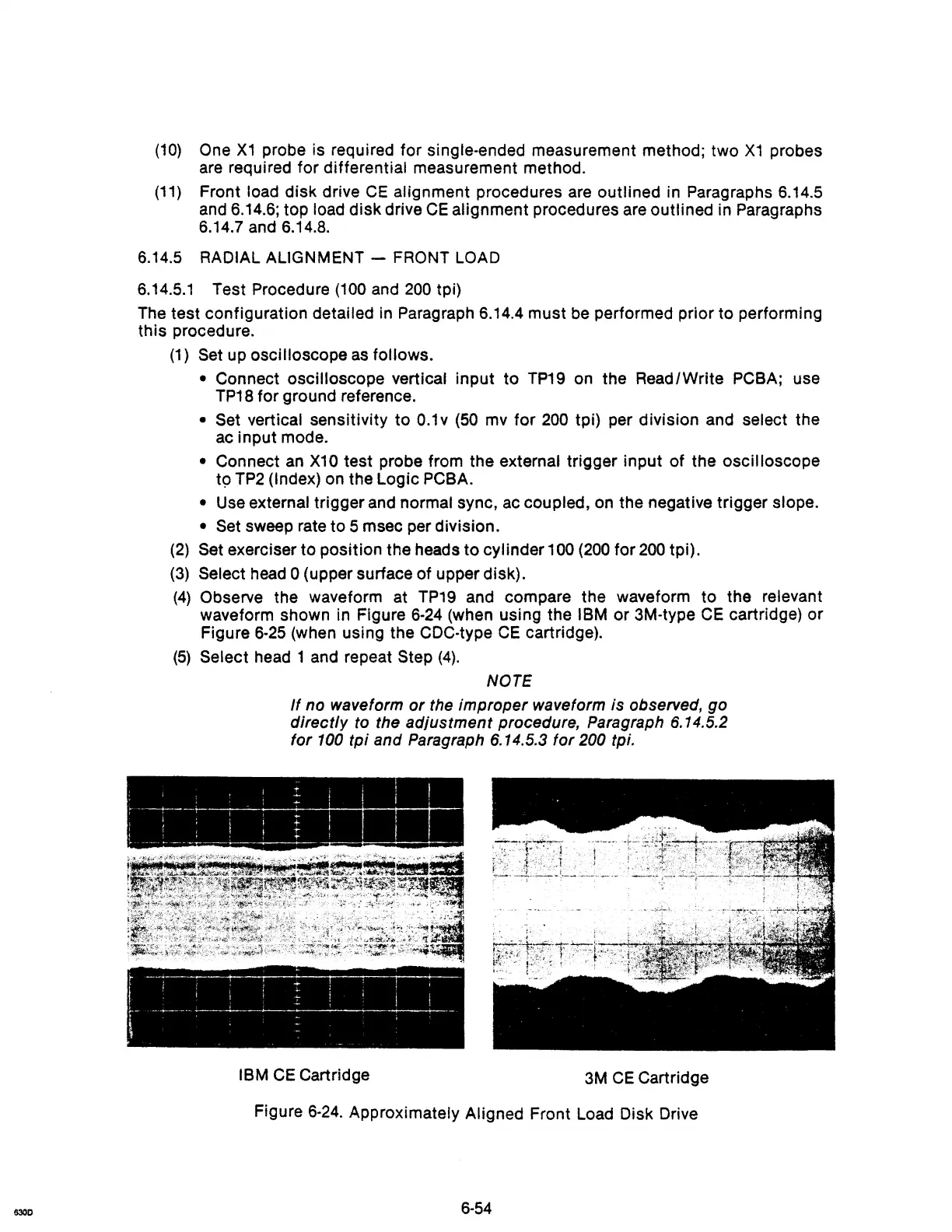
(4)
Observe the waveform at
TP19
and compare the waveform to the relevant
waveform shown in Figure
6-24
(when using the IBM or 3M-type
CE
cartridge)
or
Figure
6-25
(when using the CDC·type
CE
cartridge).
(5)
Select head 1 and repeat Step
(4).
NOTE
If
no waveform
or
the
improper
waveform
is
observed,
go
directly
to the
adjustment
procedure, Paragraph 6.14.5.2
for
100
tpi
and Paragraph 6.14.5.3
for
200 tpi.
r
~~-~---
+--,-_-~,~~
1 I
:::
i I I I
r .
-------~-:-
+,
-
IBM
CE
Cartridge
3M
CE
Cartridge
Figure
6-24.
Approximately Aligned Front Load Disk Drive
6-54