6.14.7 RADIAL
ALIGNMENT-TOP
LOAD
.
Paragraph
6.14.7.1
describes the test procedure for radial alignment to top load
100
tpi and
200
tpi 03000 disk drives; Paragraphs 6.14.7.2 and 6.14.7.3 describe the adjustment
procedures for radial
alignment of top load
100
tpi
and
200
tpi 03000 disk drives,
respectively.
6.14.7.1
Test Procedure
(100
and
200
tpi)
(1)
Set up oscilloscope
as
follows.
• Connect oscilloscope vertical input to
TP19
on the Read/Write PCBA.
•
Connect oscilloscope ground to
TP18
on
the
Read
/Write PCBA.
• Set
vertical sensitivity to
50
mv
per division and select the
ac
input mode.
• Connect a
X10
test probe from the external trigger input
of
the oscilloscope to
TP2
(Index)
on
the Logic PCBA.
•
Use
external trigger, and normal sync, ac-coupled
on
the negative trigger
slope.
• Set sweep rate to 5 msec per division.
(2)
Set the exerciser
to
position heads
as
follows.
o 100 tpi Models
• Cyl inder
73
o
200
tpi Models
• Cylinder146
(3)
Select head
O.
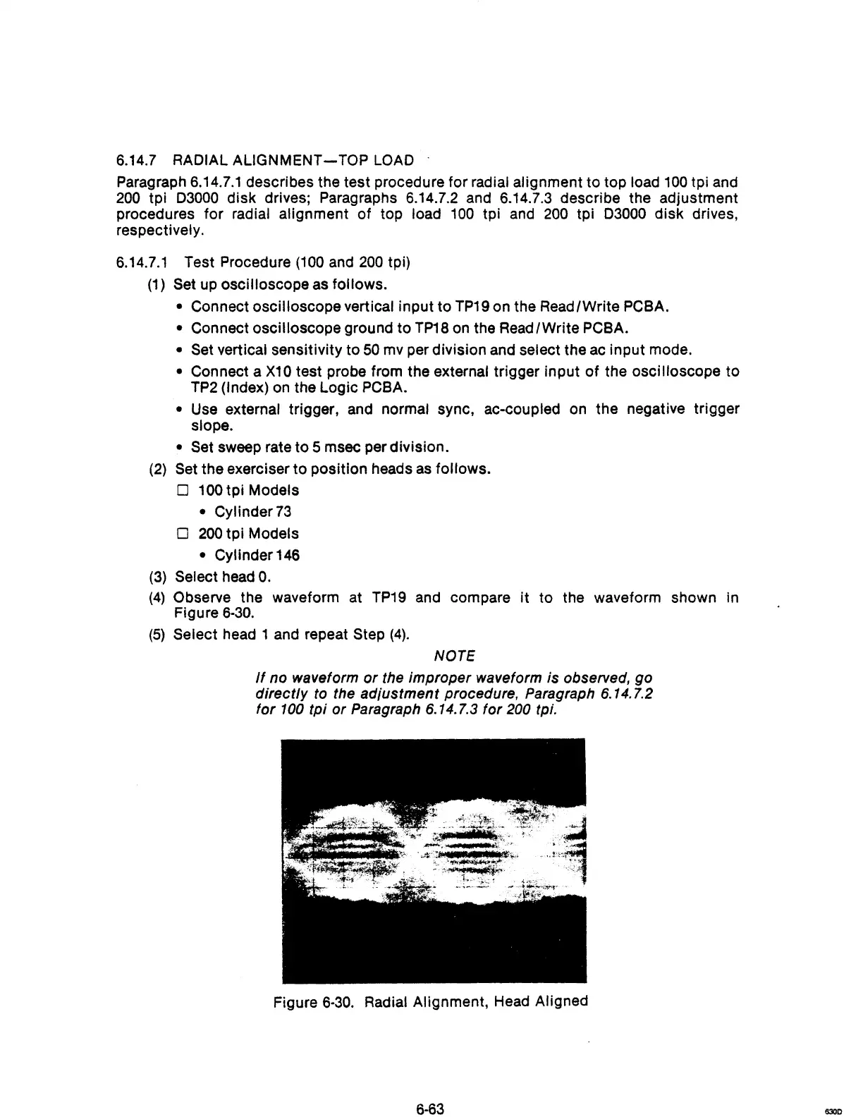
(4)
Observe the waveform at
TP19
and compare
it
to the waveform shown in
Figure
6·30.
(5)
Select head 1 and repeat Step
(4).
NOTE
If
no waveform
or
the improper waveform is observed, go
directly
to
the adiustment procedure, Paragraph 6.14.7.2
for
100
tpi or Paragraph 6.14.7.3 for 200 tpi.
Figure
6·30.
Radial Alignment, Head Aligned
6·63
6300