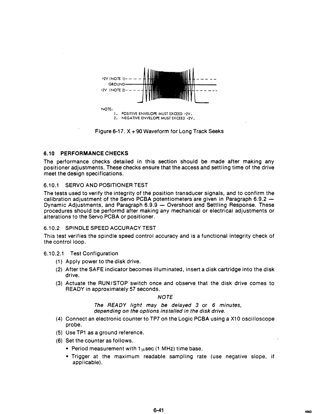
+2V
(NOTE
1)-
- - -
GROUND----++*,
-2V (NOTE
2)-
- - -
NOTE:
I.
POSITIVE
ENVELOPE
MUST
EXCEED
+2V.
2.
NEGA
TIVE
ENVELOPE
MUST
EXCEED
-2V.
Figure 6-17. X + 90 Waveform
for
Long Track Seeks
6.10
PERFORMANCE CHECKS
The performance checks detailed in
this
section
should
be made
after
making
any
pOSitioner
adjustments.
These checks ensure
that
the access and
settling
time
of
the drive
meet
the
deSign
specifications.
6.10.1 SERVO AND POSITIONER TEST
The
tests
used
to
verify the
integrity
of
the
position
transducer
signals,
and
to
confirm
the
calibration
adjustment
of
the Servo PCBA
potentiometers
are given in Paragraph 6.9.2 -
Dynamic
Adjustments,
and Paragraph 6.9.9 - Overshoot and
Settling
Response. These
procedures
should
be performd
after
making any mechanical
or
electrical
adjustments
or
alterations
to
the Servo PCBA
or
pOSitioner.
6.10.2 SPINDLE SPEED ACCURACY TEST
This test verifies
the
spindle
speed
control
accuracy and is a
functional
integrity
check
of
the
control
loop.
6.10.2.1
(1
)
(2)
Test
Configuration
Apply
power
to
the
disk
drive.
After
the SAFE
indicator
becomes
illuminated,
insert a
disk
cartridge
into
the
disk
drive.
(3)
Actuate
the
RUN I STOP
switch
once and observe that the
disk
drive
comes
to
READY in
approximately
57
seconds.
NOTE
The
READY
light
may be delayed 3
or
6 minutes,
depending on the
options
installed
in the
disk
drive.
(4) Connect
an
electronic
counter
to
TP7 on the
Logic
PCBA using a
X10
oscilloscope
probe.
(5)
Use
TP1
as a ground reference.
(6) Set the
counter
as
follows.
• Period measurement
with
1
f-Lsec
(1
MHz)
time
base.
• Trigger at the
maximum
readable
sampling
rate (use negative slope,
if
applicable).
6-41
8300