830D
6.18 MAGNETIC TRANSDUCER
GAP
Magnetic transducers
are
used
in
one place
on
front load models, and are used in two
places
on
top load models.
In
each case the distance between the transducer pole tip and
its respective rotating surface must
be
precisely controlled to produce acceptable signal
levels.
Paragraphs 6.18.1 and 6.18.2 describe the test
and
adjustment procedures for the upper
and lower transducers, respectively,
on
top loading disk drives. Paragraph 6.18.3 provides
test and adjustment instructions for front loading disk drives.
6.18.1
UPPER
TRANSDUCER
TEST
AND ADJUSTMENT -
TOP
LOAD MODELS
Extend the unit forward out of the rack and install the Adapter Bowl Setup Tool
(PERTEC
Part No.1
03619-01)
onto the spindle cone. Exercise care to ensure that cone
and
tool
are
clean
and
free
of
dirt.
CAUTION
WHEN GAUGING
GAP
CLEARANCE, ENSURE THAT NO
DAMAGE
IS
MADE
TO
THE SENSING TIP
OF
THE
TRANSDUCER
BY
THE FEELER GAUGE.
A feeler gauge
Is
used to measure the gap distance between the transducer pole
tip
and
the tool.
See
Figure 6-35.
Each
adapter bowl setup tool will have marked
on
it
a calibration
value to be added to the nominal feeler gauge value.
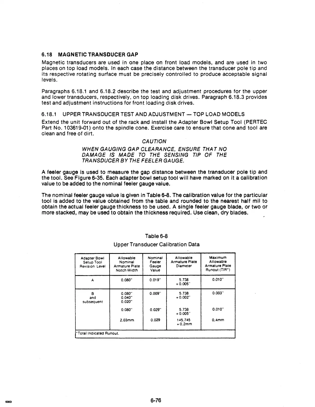
The
nominal feeler gauge value is given in Table 6-8. The calibration value for the particular
tool is added to the value obtained from the table and rounded
to
the nearest half mil to
obtain the actual feeler gauge thickness to
be
used. A single feeler gauge blade, or two or
more stacked, may
be
used
to
obtain the thickness required. Use clean, dry blades.
Table
6-8
Upper Transducer Calibration Data
Adapter Bowl
Allowable
Nominal
Allowable
Maximum
Setup
Tool
Nominal
Feeler
Armature Plate
Allowable
Revision Level
Armature Plate
Gauge
Diameter
Armature Plate
Notch Width
Value
Runout
(TlR')
A
0.080"
0.019"
5.738
0.010"
+0.005"
B
O.OSO"
0.009"
5.738
0.003"
and
0.040"
+0.002"
subsequent
0.020"
0.080" 0.029"
5.738
0.010"
+0.005"
2.03mm 0.029
145.745 0.4mm
+0.2mm
'Totallndicated
Runout.
6-76