If a strobe pulse is issued to the disk drive when the positioner is executing a previous
command (and the
BUSY
SEEKING line is low), then the results will be
as
follows: the new
operation
will not
be
commenced; the operation currently in progress will continue to
completion; and,
an
indication
of
an
illegal address will
be
given on the ILLEGAL
CYLINDER
ADDRESS
line.
3.16.5
CYLINDER DEMAND ADDRESS
(9
LINES)
These lines specify the cylinder address for accessing a specific cylinder. The address is
represented by the binary value with a
low logic level corresponding to a binary one.
The most significant bit for
203
cylinder models is bit number
7;
the most significant
bit
for
406
cylinder models is the address extension bit. The least significant bit for all models
is
bit
number
O.
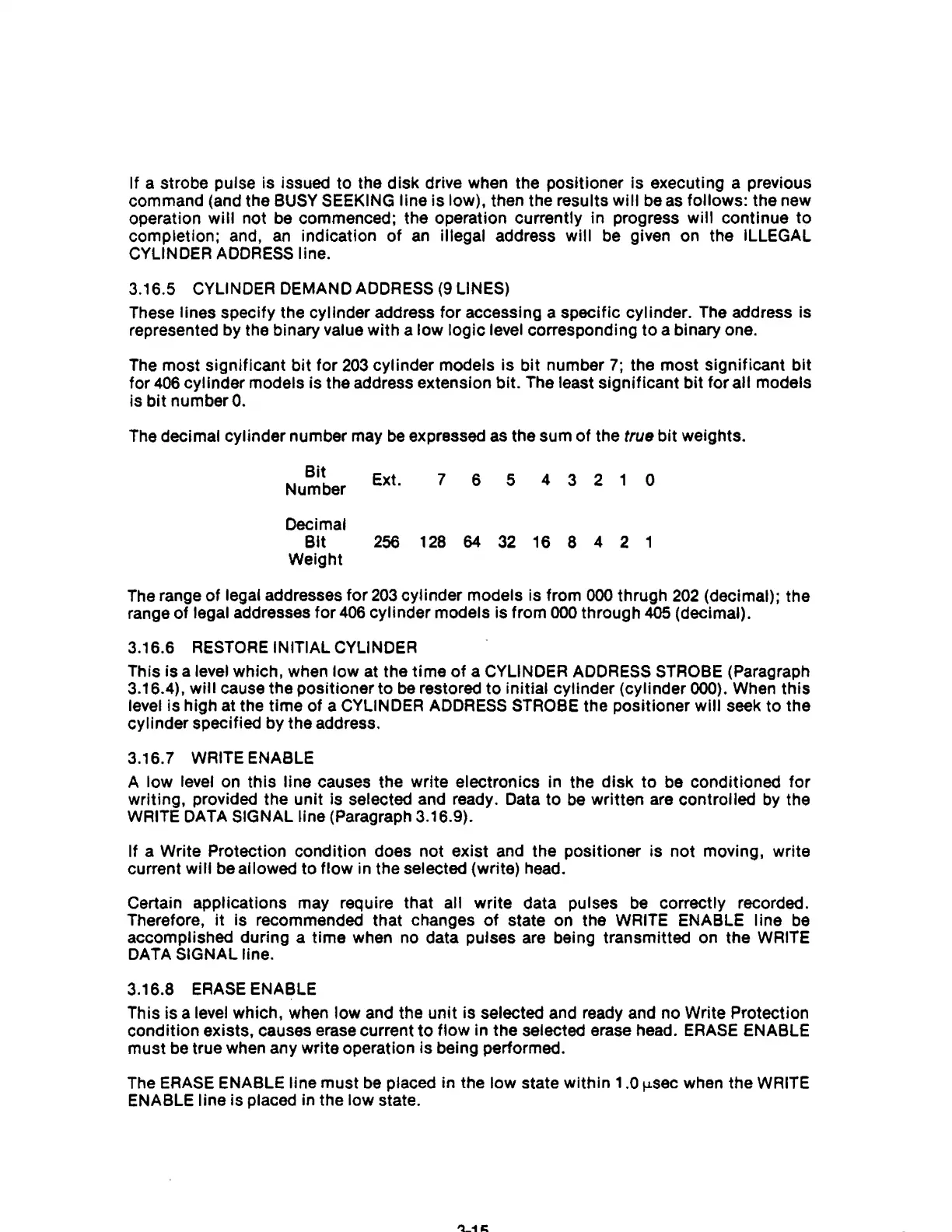
The
decimal cylinder number may
be
expressed
as
the sum of the true bit weights.
Bit
Number
Decimal
Ext.
7
6 5
4 3 2 1 0
Bit
256
128
64
32
16 8 4 2 1
Weight
The
range
of
legal addresses for
203
cylinder models is from
000
thrugh
202
(decimal); the
range of
legal addresses for
406
cylinder models is from
000
through
405
(decimal).
3.16.6
RESTORE
INITIAL CYLINDER
This is a level which, when low at the time
of
a CYLINDER ADDRESS STROBE (Paragraph
3.16.4),
will cause the positioner to be restored to initial cylinder (cylinder 000). When this
level is high at the time of a CYLINDER
ADDRESS
STROBE the positioner will seek to the
cylinder specified by the address.
3.16.7
WRITE ENABLE
A
low level
on
this line causes the write electronics in the disk to be conditioned for
writing, provided the unit is selected and ready. Data to
be
written
are
controlled
by
the
WRITE DATA SIGNAL line (Paragraph 3.16.9).
If a Write Protection condition does not exist and the positioner is not moving, write
current
will be allowed to flow in the selected (write) head.
Certain applications may require that
all write data pulses
be
correctly recorded.
Therefore,
it
is recommended that changes
of
state on the WRITE ENABLE line
be
accomplished during a time when
no
data pulses
are
being transmitted on the WRITE
DATA SIGNAL line.
3.16.8
ERASE
ENABLE
This is a
level which, when low and the unit is selected and ready and no Write Protection
condition exists, causes erase current
to
flow in the selected erase head.
ERASE
ENABLE
must be true when any write operation is being performed.
The
ERASE
ENABLE line must
be
placed in the low state within 1.0
!-Lsec
when the WRITE
ENABLE line is placed in the low state.