ClOCk
No.
01
02
03
04
05
06
07
08
09
10
11
12
13
14
15
16
17
18
19
20
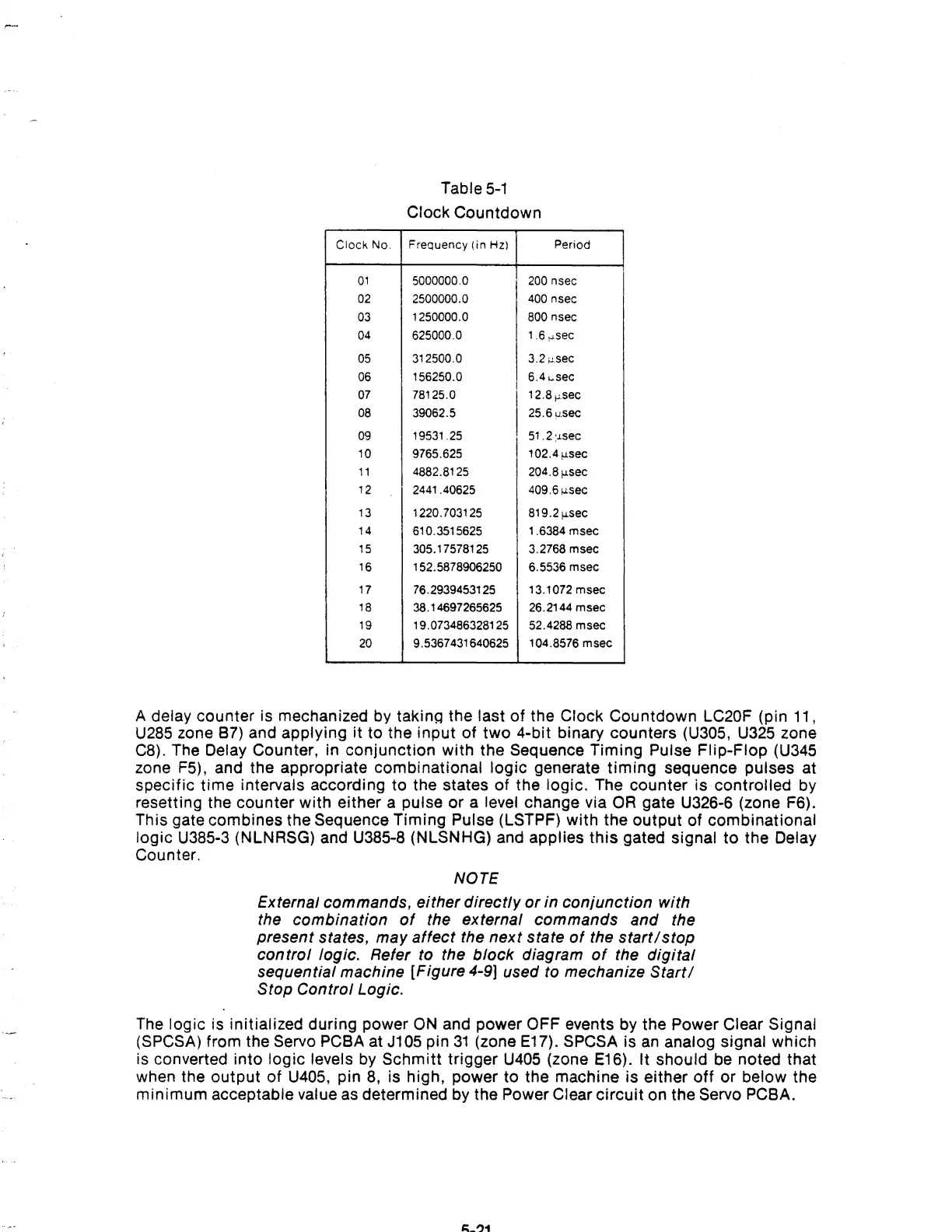
Table
5-1
Clock Countdown
Frequency
(in
Hz) Period
5000000.0 200 nsec
2500000.0 400 nsec
1250000.0 800 nsec
625000.0
1.6 ",sec
312500.0
I
3.2
,,-sec
156250.0 6.4
~sec
78125.0
I
12.8
p'sec
39062.5
25.6usec
19531.25 51.2
:J.sec
9765.625 102.4fJ.
s
ec
4882.8125 204.8fJ.sec
2441.40625 409.6>J.sec
1220.703125 819.2>J.sec
610.3515625 1.6384 msec
305.17578125 3.2768 msec
152.5878906250
6.5536 msec
76.2939453125
13.1072msec
38.14697265625
26.2144
msec
19.073486328125 52.4288
msec
9.5367431640625 104.8576
msec
I
A delay counter is mechanized by takinQ the last of the Clock Countdown LC20F (pin 11,
U285
zone 87) and applying it to the input
of
two
4-bit binary counters (U305, U325 zone
C8). The
Delay Counter, in conjunction with the Sequence Timing Pulse Flip-Flop (U345
zone F5), and the appropriate combinational
logic generate
timing
sequence pulses at
specific time intervals according
to
the states
of
the logic. The counter is controlled by
resetting the counter with either a pulse
or
a level change via
OR
gate
U32S-S
(zone
FS).
This gate combines the Sequence Timing Pulse (LSTPF)
with
the output of combinational
logic U385-3 (NLNRSG) and U385-8 (NLSNHG) and applies
this
gated signal
to
the Delay
Counter.
NOTE
External commands, either directly
or
in conjunction with
the combination
of
the external commands and the
present states, may affect the next state
of
the
start/stop
control
logic. Refer to the block diagram
of
the
digital
sequential machine [Figure 4-9] used to mechanize
Start/
Stop Control Logie.
The
logic is initialized during power
ON
and power OFF events by the Power Clear Signal
(SPCSA)
from the Servo PC8A at J105 pin
31
(zone E17). SPCSA is
an
analog Signal which
is converted into
logic levels
by
Schmitt trigger
U405
(zone
E1S).
It should be noted that
when the output of
U405, pin
8,
is high, power to the machine is either
off
or
below the
minimum acceptable value
as
determined by the Power Clear
circuit
on the Servo PC8A.