6.12.2 'ONES' WINDOW SETTING
6.12.2.1 Test Configuration
(1)
Remove the interface connector and terminator
PCBA
from connector
J101
and
J102
on the Logic PCBA.
(2)
Connect a disk exerciser having read/write capability
to
J101
or J102
on
the Logic
PCBA.
(3)
Apply power to the exerciser and the disk drive. Observe that the
READY
indicator
is
illuminated; allow a 5-minute warm up period.
(4)
Write
an
all-zeros pattern via the disk exerciser.
(5)
Connect oscilloscope Channel 1 probe
to
TP25.
Connect the test probe ground
clip to ground reference
TP17.
(6)
Set oscilloscope Channel 1 sensitivity to
0.1
Ov
per division.
(7)
Set sync to internal, normal mode.
(8)
Set oscilloscope to trigger
on
the positive slope
of
RPN.
(9)
Connect oscilloscope Channel 2 probe to
TP23.
Connect the
te~t
probe ground
clip to ground reference
TP17.
(10)
Set oscilloscope Channel 2 sensitivity to
0.1
Ov
per division.
6.12.2.2 Test And Adjustment Procedure (Long)
(1)
Observe 'ones' window on oscilloscope Channel 2
(TP23)
as shown in Figure 6-19.
(2)
Measure the adjusted internal, i.e., leading edge
of
RPN
TP25
to trailing edge
of
'ones' window
TP23.
(3)
If the pulsewidth is not within
.:1:.5
nsec
(2400
rpm)
or
.:1:.8
nsec
(1500
rpm) of
setting,
listed
in
Table 6-5, adjust
R115
until readings
are
within
.:1:.3
nsec
(2400
rpm)
or
.:1:.5
nsec
(1500
rpm).
6.12.2.3 Test And Adjustment Procedure (Short)
(1)
Write all 'ones' pattern via the disk exerciser.
(2)
Observe 'ones' window
on
oscilloscope Channel 2
(TP23)
as shown in Figure 6-19.
(2)
Measure the adjusted interval, i.e., leading edge
of
RPN
TP25
to trailing edge
of
'ones' window (TP23).
(4)
If the pulsewidth is not within
±o5
nsec
(2400
rpm)
or
.:1:.8
nsec
(1500
rpm) of
setting listed in
Table 6-5, adjust
R113
until readings are within =.3 nsec
(2400
rpm)
or
::
3 nsec
(1500
rpm).
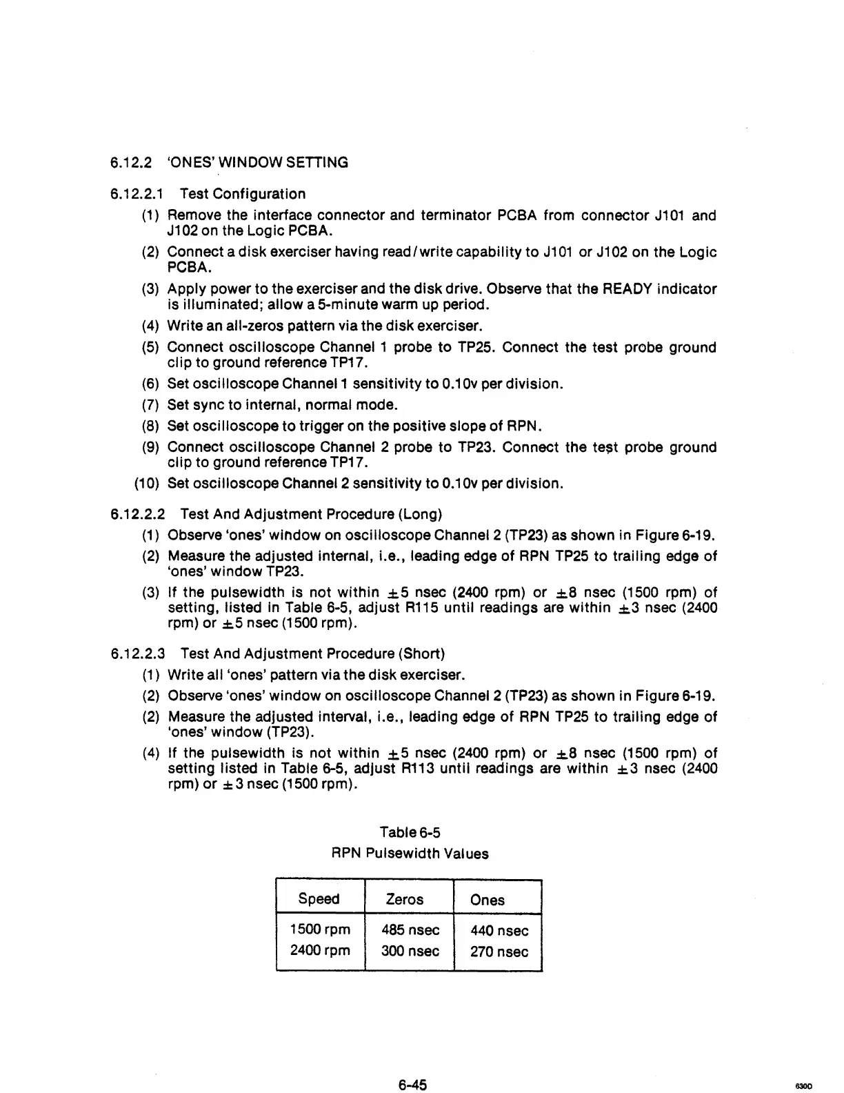
Table 6-5
RPN
Pulsewidth Values
Speed
Zeros
Ones
1500 rpm
485
nsec
440
nsec
2400
rpm
300
nsec
270
nsec
6-45
6300