6.9.9 OVERSHOOT AND SETTLING
RESPONSE
PROCEDURE
The
following steps are used to measure the overshoot and settling response of the
positioner.
6.9.9.1 Test Configuration
(1)
Prepare the positioner as described in Paragraph 6.9.1.
(2)
Set the oscilloscope
as
follows.
• Set
Channel 1 sensitivity to 0.2v per division.
• Connect Channel 1
X10
test probe
to
TP20.
• Set Channel 2 sensitivity to 0.2v per division.
• Connect Channel 2
X10
test probe
to
TP12
on the Logic PCBA (Busy Signal
NLBSXG).
• Set
sweep. rate; refer to Table 6-4, Step 1 (Step 7
for
200
tpi).
• Set channel select switch to Chopped mode.
• Set internal sync to Channel
2.
(3)
Set disk exerciser as follows.
• Set exerciser to perform repetitive track seek; refer to Table 6-4, Step 1 (Step 7
for
200
tpi).
• Set Data mode switch to R/W.
• Set exerciser to Auto.
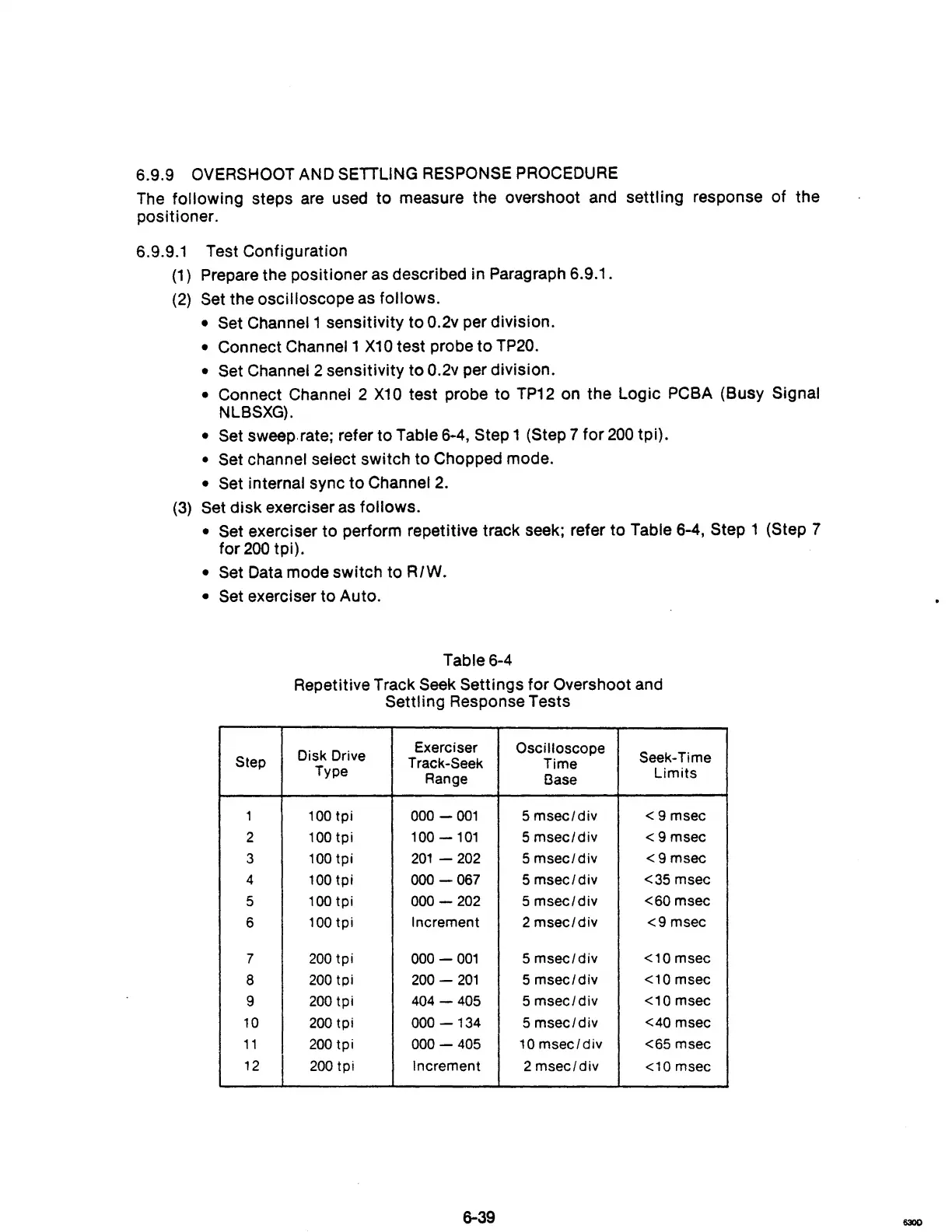
Table 6-4
Repetitive Track
Seek Settings for Overshoot and
Settling Response Tests
Disk Drive
Exerciser
Oscilloscope
Seek-Time
Step
Track-Seek
Time
Type
Range
l3ase
Limits
1
100
tpi
000 -
001
5
msec/div
<9
msec
2
100tpi
100
-101
5
msec/div
<9
msec
3
100
tpi
201
- 202
5
msec/div
<9msec
4
100
tpi
000
-067
5
msec/div
<35 msec
5
100
tpi
000
-
202
5
msec/div
<60
msec
6
100
tpi
Increment 2
msec/div
<9
msec
7
200
tpi
000 -
001
5
msec/div
<10
msec
8
200
tpi
200
-
201
5
msec/div
<10 msec
9
200
tpi
404
-
405
5
msec/div
<10
msec
10
200
tpi
000
-134
5
msec/div
<40 msec
11
200
tpi
000 -
405
10
msec/div
<65 msec
12
200
tpi Increment 2
msec/div
<10 msec
6-39
630D