830D
6.9.9.2 Test Procedure
(1)
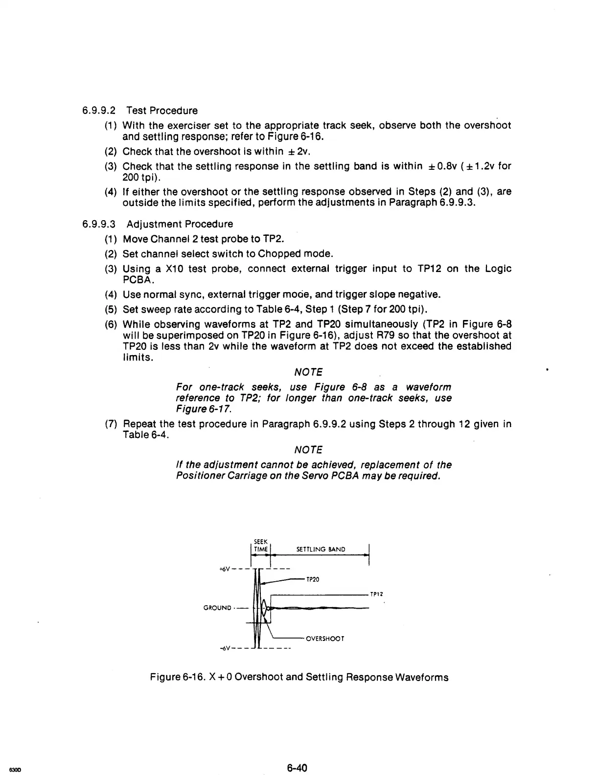
With the exerciser set to the appropriate track seek, observe both the overshoot
and
settling response; refer to Figure 6-16.
(2)
Check that the overshoot is within :I:
2v.
(3)
Check that the settling response in the settling band is within :I:
O.Bv
( :I: 1 .2v for
200
tpi).
(4)
If either the overshoot or the settling response observed in Steps
(2)
and
(3),
are
outside the
limits
specified, perform the adjustments in Paragraph 6.9.9.3.
6.9.9.3 Adjustment Procedure
(1)
Move Channel 2 test probe to TP2.
(2)
Set channel select switch to Chopped mode.
(3)
Using a
X10
test probe, connect external trigger input to
TP12
on
the Logic
PCBA.
(4)
Use
normal sync, external trigger
mOcie,
and trigger slope negative.
(5)
Set sweep rate according to Table 6-4, Step 1 (Step 7 for
200
tpi).
(6)
While observing waveforms at
TP2
and
TP20
simultaneously
(TP2
in
Figure
6-8
will
be
superimposed on
TP20
in Figure 6-16), adjust
R79
so that the overshoot at
TP20
is less than
2v
while the waveform at
TP2
does not exceed the established
limits.
NOTE
For one-track seeks, use Figure 6-8 as a waveform
reference to
TP2;
for longer than one-track seeks, use
Figure
6-17.
(7)
Repeat the test procedure in Paragraph 6.9.9.2 using Steps 2 through
12
given in
Table 6-4.
NOTE
If
the adjustment cannot be achieved, replacement
of
the
Positioner Carriage on the Servo
PCBA
may be required.
SETTLING
BAND
·1
+6V---
----
~--TP20
,---------TP1"2
GROUND·-
H·l-loI=--===------
'---OVERSHOOT
-6V---
Figure 6-16. X
+0
Overshoot and Settling Response Waveforms