6300
6.9.8.4 Test Configuration - Step 2
(1)
Set
oscilloscope
as
follows.
• Set
Channel 1 sensitivity to
O.5v
per division.
• Connect Channel 1 test probe to
TP3.
• Set sweep rate to 1 msec per division.
• Sync internal on Channel 1 , use positive trigger slope.
• Set Channel 1 ground-referenced sweep trace to the center line
of
graticule.
(2)
The
exerciser remains operating in the repetitive restore mode.
6.9.8.5 Test Procedure - Step 2
(1) Select Channel 1 .
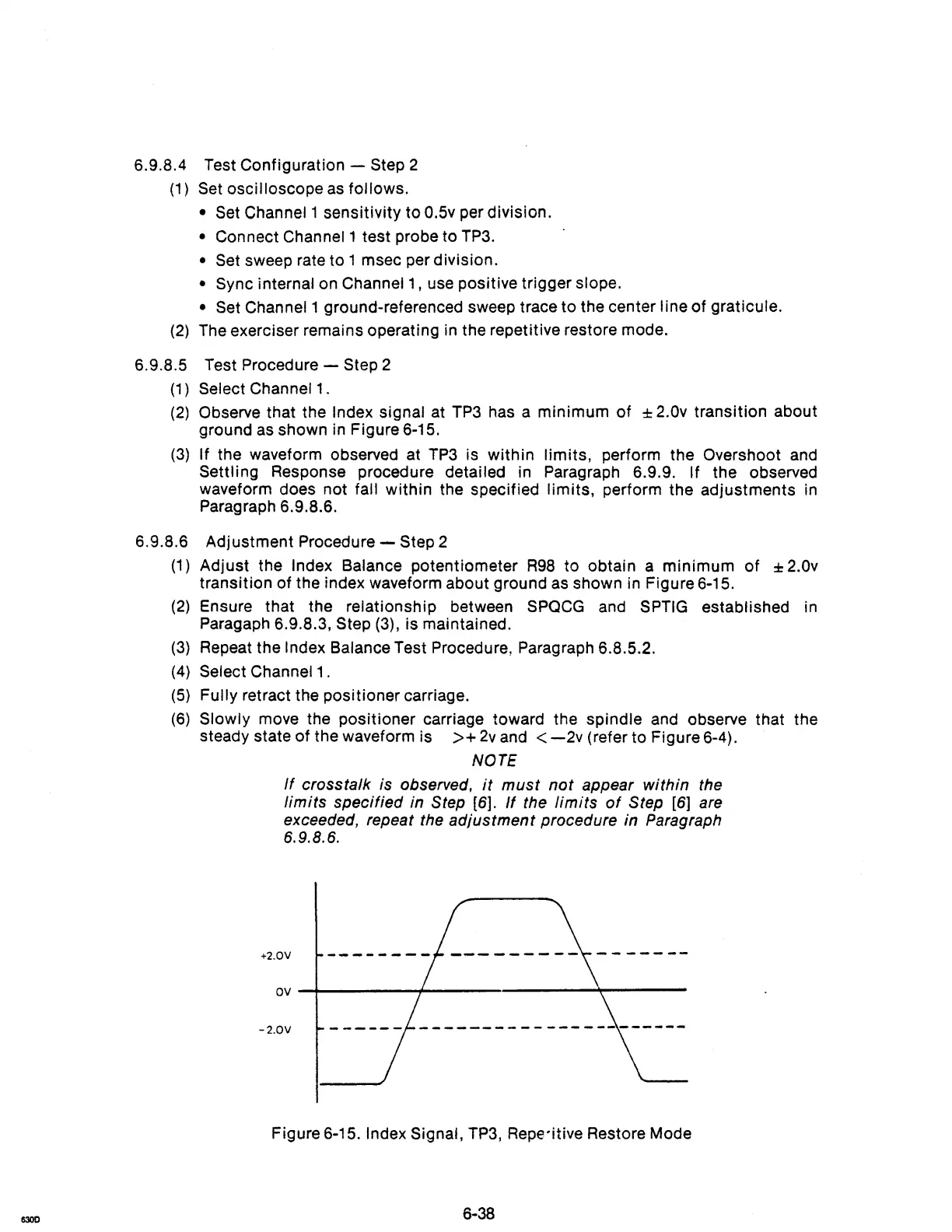
(2)
Observe that the Index signal at
TP3
has a minimum
of
± 2.0v transition about
ground
as
shown
in
Figure 6-15.
(3) If the waveform observed at
TP3
is within limits, perform the Overshoot
and
Settling Response procedure detailed in Paragraph 6.9.9. If the observed
waveform does not
fall within the specified limits, perform the adjustments
in
Paragraph 6.9.8.6.
6.9.B.6
Adjustment Procedure - Step 2
(1)
Adjust the Index Balance potentiometer
R98
to obtain a minimum of ± 2.0v
transition of the index waveform about ground
as
shown in Figure 6-15.
(2)
Ensure that the relationship between
SPQCG
and
SPTIG
established
in
Paragaph 6.9.8.3, Step (3), is maintained.
(3) Repeat the Index Balance Test Procedure, Paragraph 6.8.5.2.
(4) Select Channel
1.
(5) Fully retract the positioner carriage.
(6) Slowly move the positioner carriage toward the spindle
and
observe that the
steady state of the waveform is
>+
2v
and <
-2v
(refer to Figure 6-4).
NOTE
If
crosstalk is observed,
it
must
not
appear within the
limits specified in
Step [6].
If
the
limits
of
Step
[6]
are
exceeded, repeat the adjustment procedure in Paragraph
6.9.B.6.
+2.0V
ov~--------~~----------------~-------
-2.0V
Figure 6-15. Index Signal,
TP3,
Repe-itive Restore Mode
6-38