(3)
The high-ta-Iow transition
of
SPTIG (Transition B
of
Figure 6-13) should occur at
or
after the low-to-high transition of
SPRCG
(Transition A of Figure 6-13), i.e.,
time t2 should be greater than or equal
to
zero seconds.
(4)
If the requirements of Steps (1), (2). and
(3)
are
not satisfied, perform the
adjustment procedure outlined in Paragraph 6.9.8.3. then repeat the foregoing
steps prior to continuing
this
procedure. If adjustments to satisfy the above
requirements cannot
be
made, replacement
of
position transducer scale may
be
necessary.
(5)
Change the oscilloscope settings established in Paragraph 6.9.8.1, as follows.
• Connect Channel 2 test probe
to
TP13
.
• Sync internal on Channel 1 , use negative trigger slope.
NOTE
It
may
be
necessary
to
change the sweep rate to a more
desirable setting.
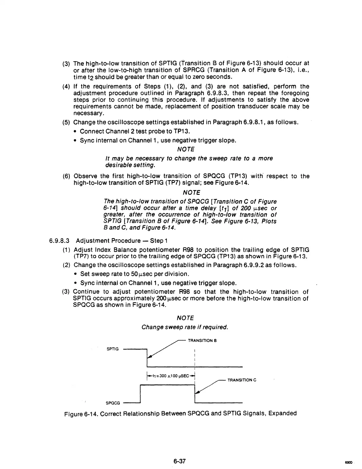
(6)
Observe the first high-ta-Iow transition
of
SPQCG (TP13) with- respect to the
high-to-Iow transition of
SPTIG
(TP7)
signal;
see
Figure 6-14.
NOTE
The
high-to-Iow transition
of
SPQCG
[Transition C
of
Figure
6-14] should occur after a time delay [t1]
of
200
jJ.sec
or
greater, after the occurrence
of
high-to-Iow transition
of
SPTlG [Transition B
of
Figure 6-14].
See
Figure 6-13, Plots
Band
C, and Figure
6-14.
6.9.8.3 Adjustment Procedure - Step 1
(1)
Adjust Index Balance potentiometer
R98
to
position the trailing edge of
SPTIG
(TP7) to occur prior to the trailing edge of
SPQCG
(TP13)
as
shown in Figure 6-13.
(2)
Change the oscilloscope settings established in Paragraph 6.9.9.2
as
follows.
• Set sweep rate to
50jJ.sec
per division.
• Sync internal on Channel 1, use negative trigger slope.
(3)
Continue to adjust potentiometer
R98
so that the high-to-Iow transition
of
SPTIG occurs approximately
200
jJ.sec
or more before the high-to-Iow transition of
SPQCG
as shown in Figure 6-14.
NOTE
Change sweep rate
if
required.
SPTIG
I
SPQCG
~
f-
t1
= 300
±.1
00
IISEc-l
LTRAN~nONC
Figure 6-14. Correct Relationship Between
SPQCG
and SPTIG Signals, Expanded
6-37