8300
PLOT
SIGNAL
J
1
LP5VA
(TP26)
OV
)~-------tl~.
2.7V
(NOMINAL)
2 038
~
_____
-oII"'1
-------------fl
~
~
(B.ASE)
ov
3
Ql7
(B.ASE)
OV
4 Q36
(COLLECTOR)
OV
5
SPCSA
ov
6
QJ5
(B.ASE)
--
OV
7
041
(SASE)
ov
2.7
V
(NOMINAL)
\---
4.8v
(NOMINAL)
I~~-----------~I~--~I
I~--~
3.3V
(NOMINAL)
"""14.-.....--APp~~X~.!..-TE----<
..
--t1
I I
;--.,
---II
1
4.JV
(NOMIN.AL)
I
1.5v
(NOMINAl)
~
~-----f~
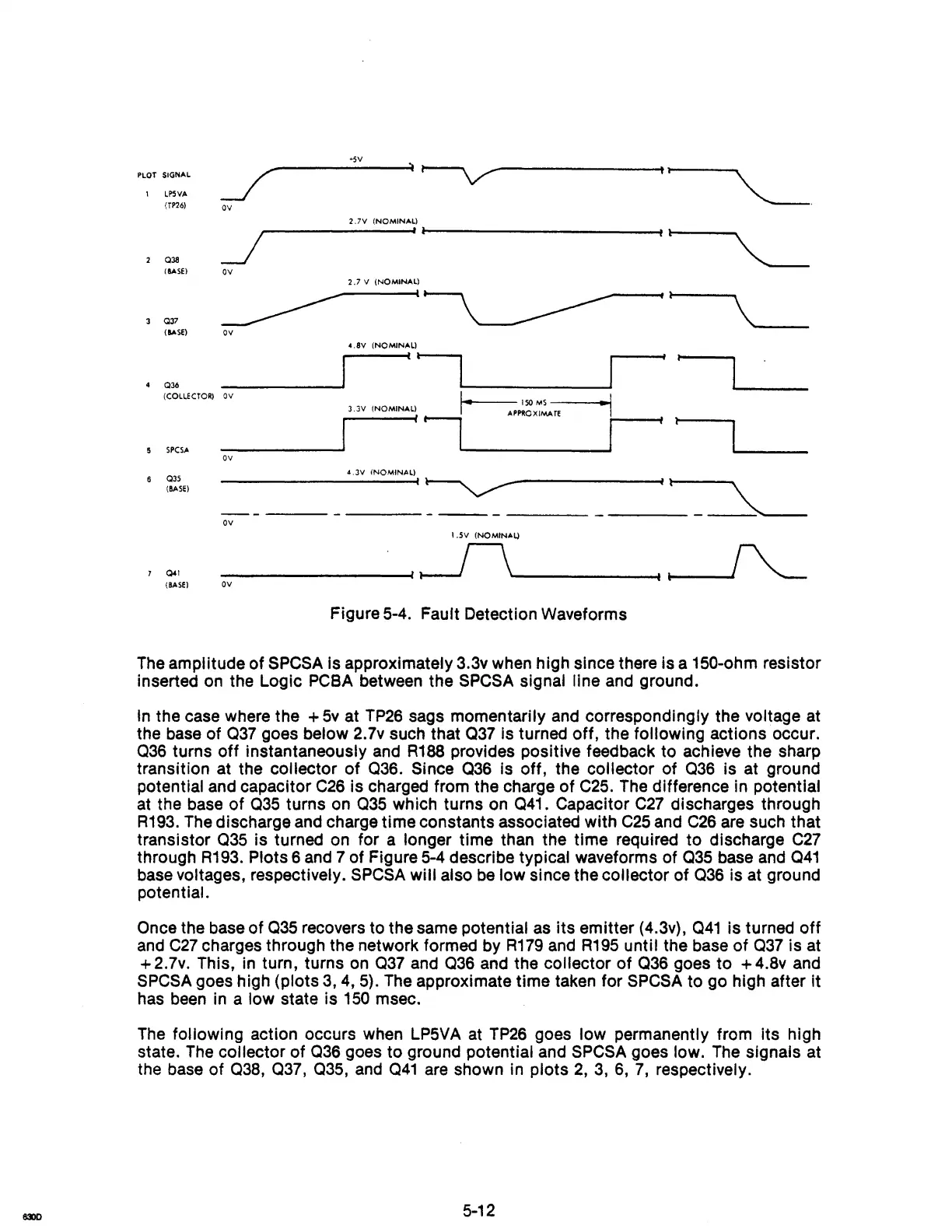
Figure 5-4. Fault Detection Waveforms
The
amplitude of
SPCSA
is approximately 3.3v when high since there is a 150-ohm resistor
inserted
on
the Logic
PCBA
between the
SPCSA
signal line and ground.
In
the case where the +
5v
at
TP26
sags momentarily
and
correspondingly the voltage at
the
base
of 037 goes below 2.7v such that 037 is turned off, the following actions occur.
036 turns
off
instantaneously and
R188
provides positive feedback to achieve the sharp
transition at the collector
of
036. Since 036 is off, the collector of 036 is at ground
potential and capacitor
C26
is charged from the charge of
C25.
The
difference in potential
at the base
of
035 turns
on
035 which turns
on
041. Capacitor
C27
discharges through
R193.
The
discharge and charge time constants associated with
C25
and
C26
are such that
transistor
035 is turned
on
for a longer time than the time required to discharge
C27
through
R193.
Plots 6
and
7 of Figure
5-4
describe typical waveforms of 035 base
and
041
base voltages, respectively.
SPCSA
will also
be
low since the collector of 036 is at ground
potential.
Once the base of 035 recovers to the same potential
as
its emitter (4.3v), 041 is turned
off
and
C27
charges through the network formed by
R179
and
R195
until the base
of
037 is at
+2.7v. This,
in
turn, turns
on
037 and 036 and the collector
of
036 goes to
+4.8v
and
SPCSA
goes high (plots
3,4,5).
The
approximate time taken for
SPCSA
to go high after it
has
been
in a low state is
150
msec.
The
following action occurs when
LP5VA
at
TP26
goes low permanently from its high
state.
The
collector
of
036 goes to ground potential and
SPCSA
goes low.
The
signals at
the base of
038, 037, 035,
and
041
are
shown in plots
2,
3,
6,
7,
respectively.
5-12