(6)
Set
oscilloscope
as
follows
• Voltage
sensitivity to 0.2v per division
if
the
X10
probe is used.
• Select dc input mode.
•
Sweep
rate to
0.1
msec per division.
•
Set
to normal trigger mode.
• .
Use
internal sync
and
set to trigger
on
negative slope.
6.6.3.2 Test Procedure
(1)
Establish test configuration described
in
Paragraph 6.6.3.1.
(2)
Select Channel 1
on
the oscilloscope.
(3)
Ground
U19A-2
(NLDMEG) on the Servo PCBA.
(4)
Apply power to the disk drive.
6.6.3.3 Adjustment Procedure
(1)
Establish test configuration described
in
Paragraph 6.6.3.1.
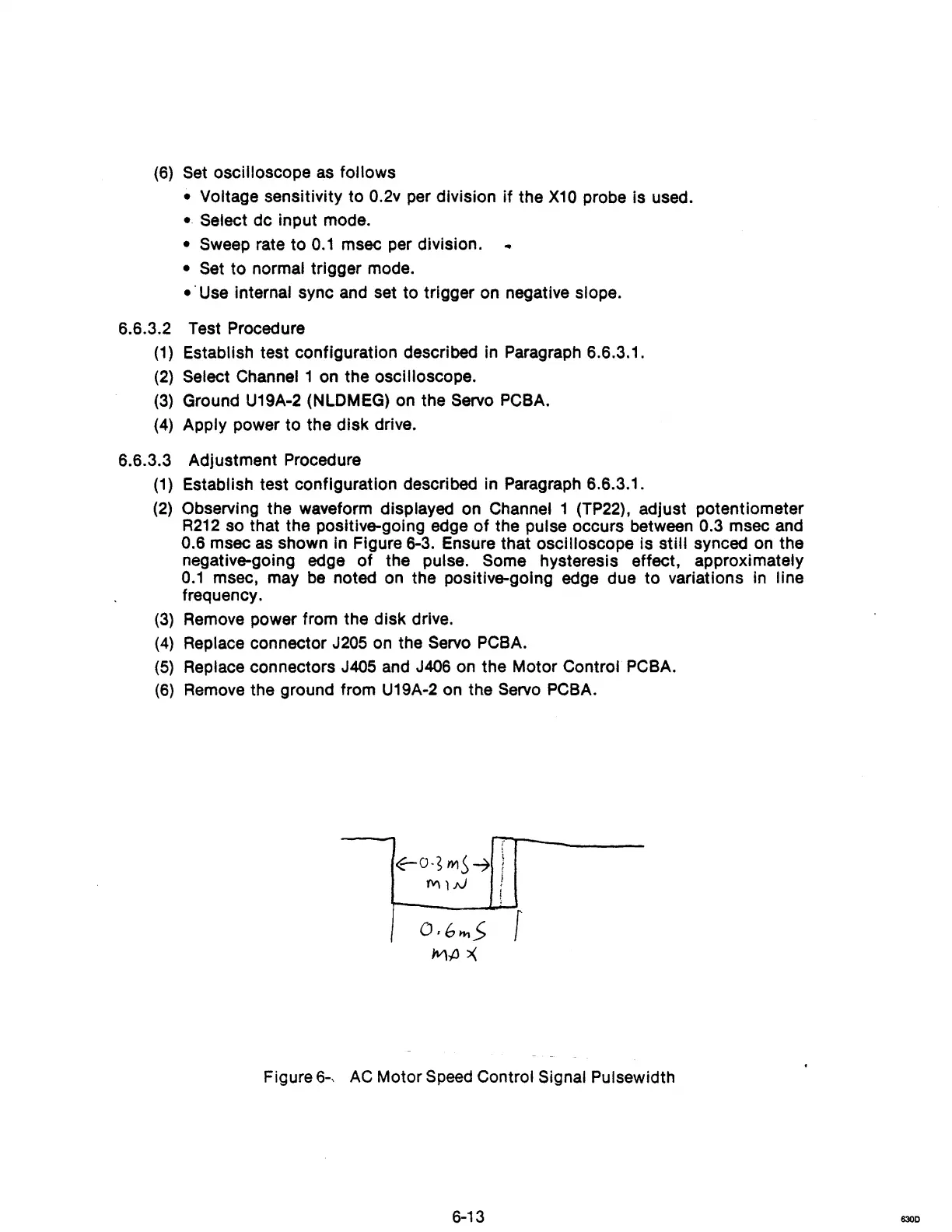
(2)
Observing the waveform displayed on Channel 1
(TP22),
adjust potentiometer
R212
so that the positive-going edge
of
the pulse occurs between 0.3 msec
and
0.6 msec
as
shown
In
Figure 6-3. Ensure that oscilloscope Is still synced
on
the
negative-going edge of the pulse.
Some hysteresis effect, approximately
0.1
msec, may
be
noted
on
the positive-going edge due to variations
in
line
frequency.
(3)
Remove
power from the disk drive.
(4) Replace connector J205
on
the Servo
PCBA.
(5) Replace connectors J405
and
J406
on
the Motor Control
PCBA.
(6)
Remove
the ground from
U19A-2
on
the
Servo
PCBA.
Figure 6-,
AC
Motor
Speed
Control Signal Pulsewidth
6-13
6300