(2)
Readjust the sensitivity of Channel 2 to 0.5v per division.
(3)
Set Channel Select switch
to
Add mode (Channel 1 plus Channel 2).
(4)
Sync internally
off
of
Channel 1 on the positive portion
of
the analog signal.
(5)
Manually move the positioner carriage back and forth, at a constant rate, through
its
full stroke.
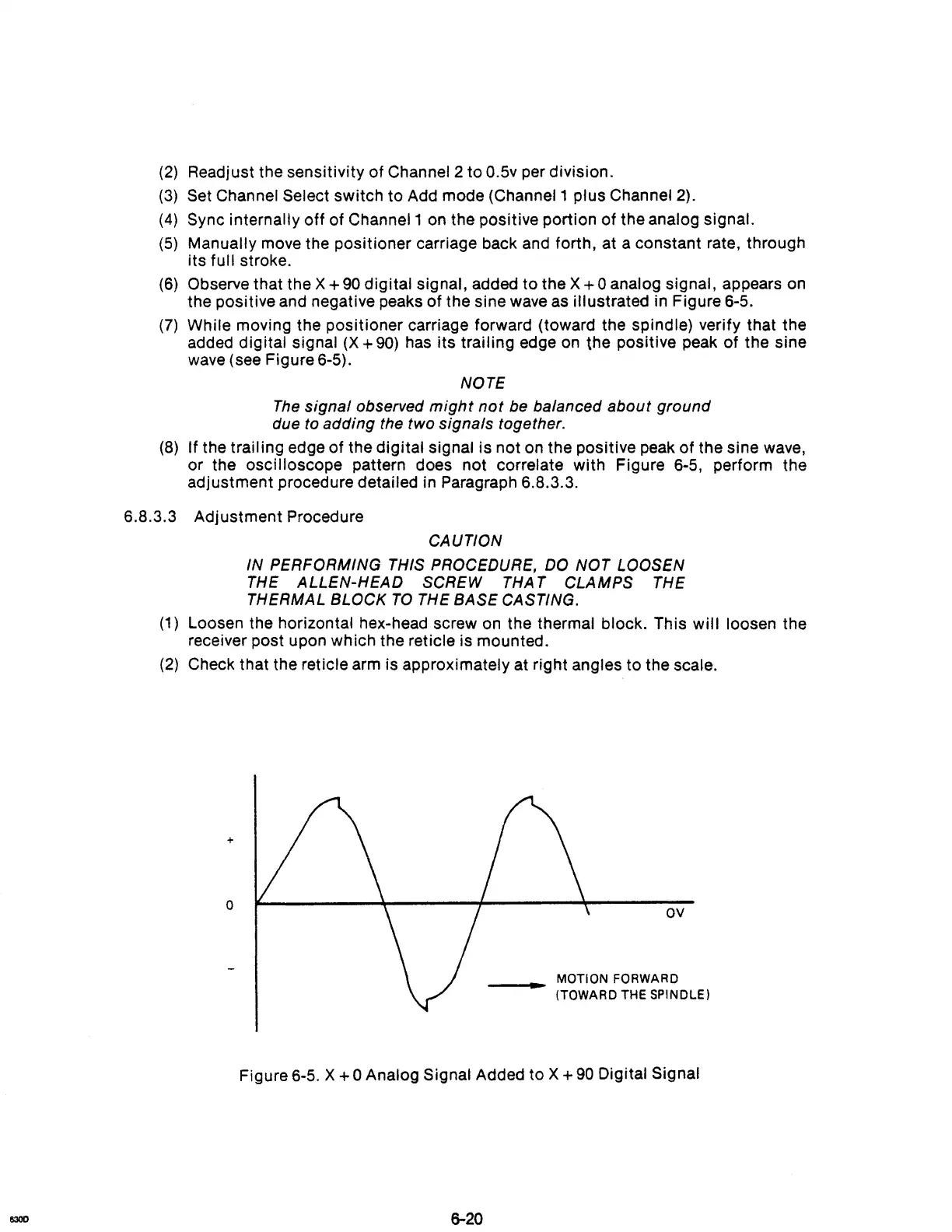
(6)
Observe that the X +
90
digital signal, added
to
the X + 0 analog signal, appears
on
the positive and negative peaks
of
the sine wave as illustrated in Figure 6-5.
(7)
While moving the positioner carriage forward (toward the spindle) verify that the
added digital signal
(X
+
90)
has its trailing edge
on
the positive peak
of
the sine
wave (see Figure 6-5).
NOTE
The
signal
observed
might
not
be balanced
about
ground
due to adding the two signals together.
(8)
If the trailing edge
of
the digital signal is not on the positive peak
of
the sine wave,
or the
oscilloscope pattern does not correlate with Figure 6-5, perform the
adjustment procedure detailed in Paragraph 6.8.3.3.
6.8.3.3 Adjustment Procedure
CAUTION
IN
PERFORMING THIS PROCEDURE, DO
NOT
LOOSEN
THE
ALLEN-HEAD
SCREW THA T
CLAMPS
THE
THERMAL
BLOCK
TO
THE
BASE
CASTING.
(1)
Loosen the horizontal hex-head screw on the thermal block. This will loosen the
receiver post upon which the reticle is mounted.
(2)
Check that the reticle arm is approximately at right angles to the scale.
+
o
OV
__
...
MOTION FORWARD
(TOWARD THE
SPINDLE)
Figure 6-5. X + 0 Analog Signal Added to X +
90
Digital Signal
6-20