(19)
Check that the waveform is balanced about ground
as
shown
in
Figure 6-8.
(20)
If the waveform observed
in
Step
(19)
is not balanced about ground, perform the
adjustment procedure given in Paragraph 6.9.2.3,
Step (6), before continuing this
procedure.
(21)
Move Channel 1 test probe
to
TP20.
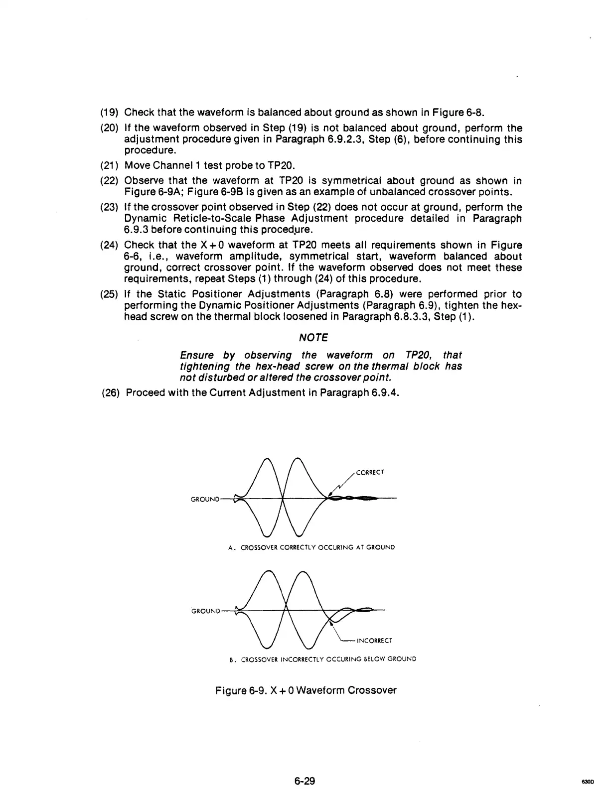
(22)
Observe that the waveform at
TP20
is symmetrical about ground
as
shown in
Figure 6-9A; Figure 6-98 is given
as
an
example of unbalanced crossover pOints.
(23)
If the crossover point observed in Step
(22)
does not occur at ground, perform the
Dynamic
Reticle-to-Scale Phase Adjustment procedure detailed in Paragraph
6.9.3 before continuing
this
proced.ure.
(24)
Check that the X + 0 waveform at
TP20
meets all requirements shown in Figure
6-6, i.e., waveform amplitude, symmetrical start, waveform balanced about
ground, correct crossover
pOint. If the waveform observed does not meet these
requirements, repeat
Steps
(1)
through
(24)
of
this
procedure.
(25)
If the Static Positioner Adjustments (Paragraph 6.8) were performed prior
to
performing the Dynamic Positioner Adjustments (Paragraph 6.9), tighten the hex-
head screw on the thermal block loosened in Paragraph 6.8.3.3,
Step (1).
NOTE
Ensure
by
observing the waveform on
TP20,
that
tightening the hex-head screw on the thermal block has
not
disturbed
or
altered the crossover point.
(26)
Proceed with the Current Adjustment in Paragraph 6.9.4.
LCORRECT
GROUND-£;;;;;:...-----4----=~~-
...
--
A.
CROSSOVER
CORRECTLY
OCCUR1NG
AT
GROUND
B.
CROSSOVER
INCORRECTLY CCCURING
BELOW
GROUND
Figure 6-9. X + 0 Waveform Crossover
6-29
6300