6300
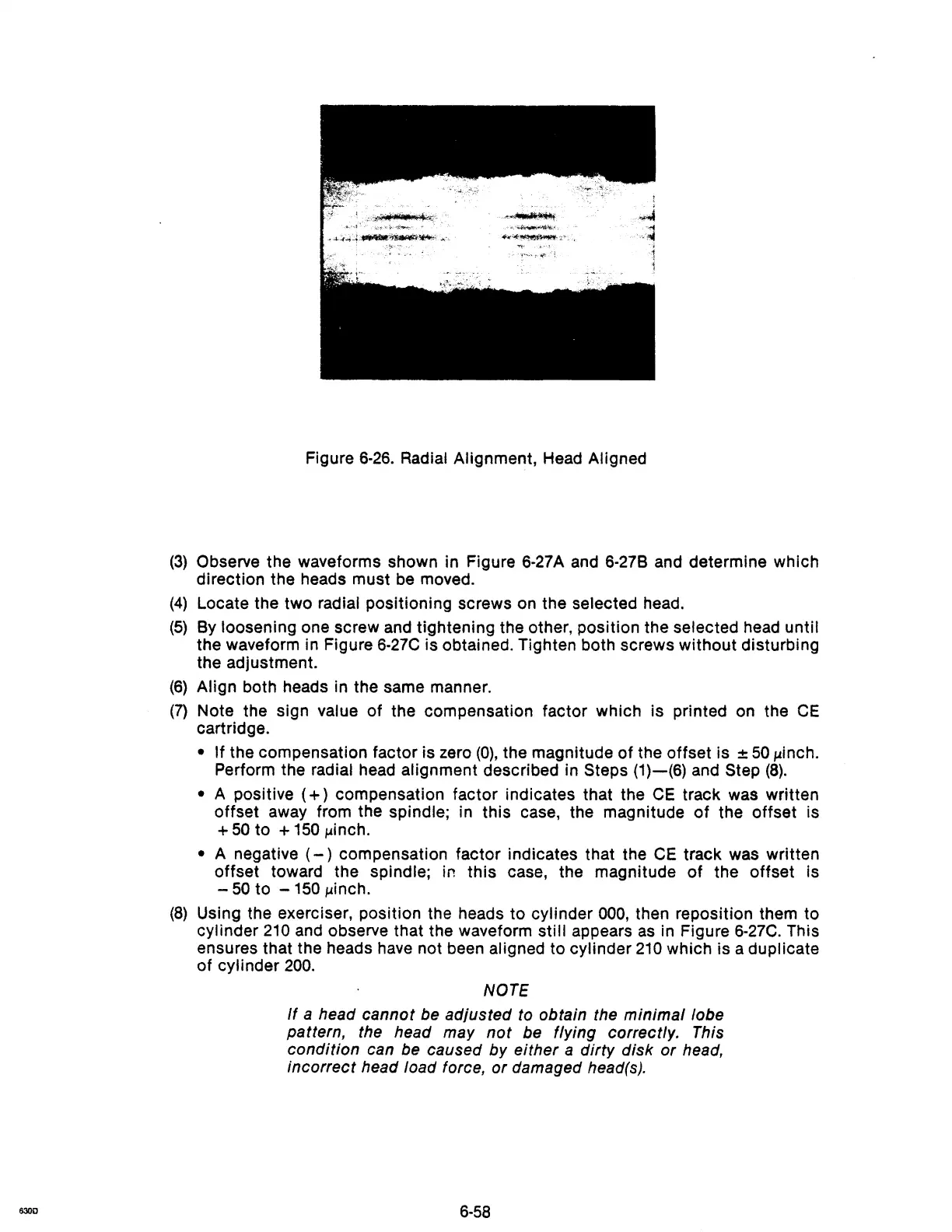
Figure
6-26.
Radial Alignment, Head Aligned
(3)
Observe the waveforms shown in Figure 6-27A and 6-27B and determine which
direction the heads must
be
moved.
(4)
Locate the two radial positioning screws on the selected head.
(5)
By
loosening one screw and tightening the other, position the selected head until
the waveform in Figure
6-27C
is obtained. Tighten both screws without disturbing
the adjustment.
(6)
Align both heads in the same manner.
(7)
Note the sign value of the compensation factor which is printed on the
CE
cartridge.
• If the compensation factor is zero
(0),
the magnitude of the offset is ±
50
J.linch.
Perform the radial head alignment described in Steps
(1)-(6)
and Step
(8).
• A positive
(+)
compensation factor indicates that the
CE
track was written
offset away from the
spindle; in this case, the magnitude
of
the offset is
+
50
to +
150
J.linch.
• A negative
(-)
compensation factor indicates that the
CE
track was written
offset toward the
spindle; in
this
case, the magnitude
of
the offset is
-
50
to -
150
J.linch.
(8)
Using the exerciser, position the heads
to
cylinder
000,
then reposition them to
cylinder
210
and observe that the waveform still appears
as
in Figure
6-27C.
This
ensures that the heads have not been
aligned to cylinder
210
which is a duplicate
of cylinder
200.
NOTE
If
a head cannot be adjusted to obtain the minimal lobe
pattern, the head may
not
be flying correctly. This
condition can be caused by either
a dirty disk or head,
incorrect head load force,
or
damaged head(s).
6-58