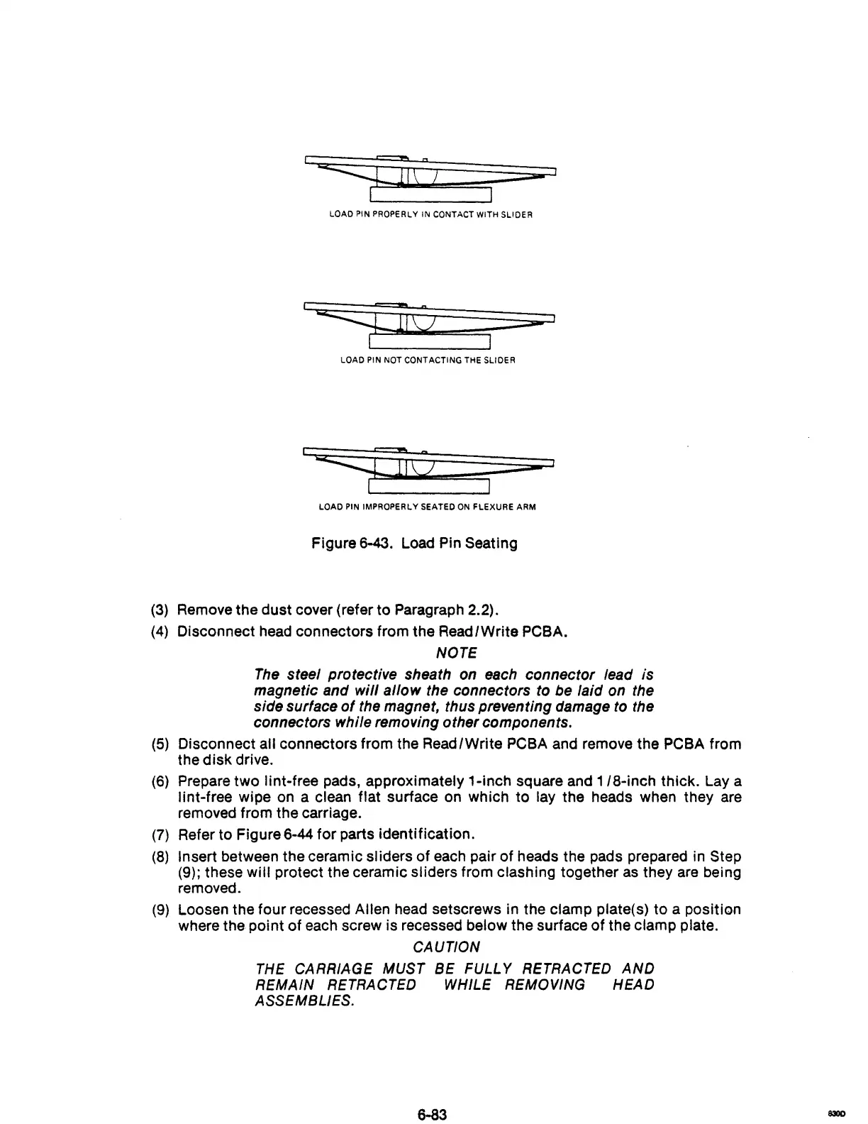
LOAD PIN PROPERLY IN CONTACT WITH SLIDER
LOAD
PIN
NOT CONTACTING THE SLIDER
1
LOAD
PIN
IMPROPERLY SEATED
ON
FLEXURE ARM
Figure 6-43. Load Pin Seating
(3) Remove the dust cover (refer to Paragraph 2.2).
(4)
Disconnect head connectors from the ReadlWrite PCBA.
NOTE
The
steel protective sheath on each connector lead is
magnetic and
will allow the connectors to be laid on the
side surface
of
the magnet, thus preventing damage to the
connectors while removing other components.
(5)
Disconnect all connectors from the ReadlWrite PCBA and remove the PCBA from
the
disk
drive.
(6)
Prepare
two
lint-free pads, approximately 1-inch square and
1/8-inch
thick. Lay a
lint-free wipe on a clean flat surface on which to lay the heads when they are
removed from the carriage.
(7)
Refer to Figure 6-44
for
parts identification.
(8)
Insert between the ceramic sliders
of
each pair of heads the pads prepared in Step
(9); these
will protect the ceramic sliders from clashing together
as
they
are
being
removed.
(9)
Loosen the four recessed Allen head setscrews in the clamp plate(s) to a position
where the point
of
each screw is recessed below the surface
of
the clamp plate.
CAUTION
THE
CARRIAGE
MUST
BE
FULLY
RETRACTED
AND
REMAIN
RETRACTED
WHILE
REMOVING
HEAD
ASSEMBLIES.
6-83
830D