6300
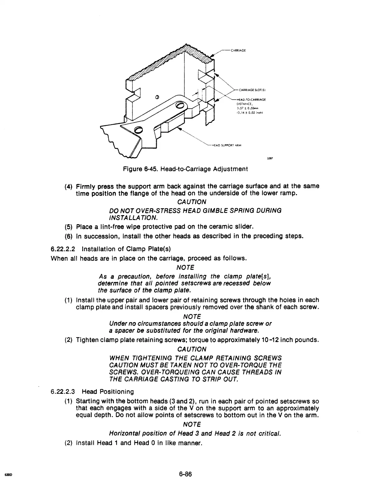
CARRIAGE
CARRIAGE SLOTiS)
HEAO· TO.cARRIAGE
DISTANCE.
3.57
1; O.sOmm
IQ.14
±
0.02
inch}
~
~~EAO
SUPPORT
ARM
Figure 6-45. Head-to-Carriage
Adjustment
3287
(4)
Firmly
press
the
support
arm back
against
the
carriage surface and at
the
same
time
position
the
flange
of
the
head
on
the
underside
of
the
lower
ramp.
CAUTION
DO
NOT
OVER-STRESS HEAD
GIMBLE
SPRING DURING
INSTALLA TION.
(5) Place a
lint-free
wipe
protective pad on
the
ceramic slider.
(6) In succession, Install
the
other
heads as described
in
the
preceding steps.
6.22.2.2 Installation
of
Clamp Plate(s)
When
all heads are In place on
the
carriage, proceed as
follows.
NOTE
As
a precaution. before installing the clamp plate[s].
determine that
al/ pointed setscrews
are
recessed below
the surface
of
the clamp plate.
(1) Install
the
upper
pair
and
lower
pair
of
retaining screws
through
the
holes in each
clamp
plate and
install
spacers previously removed over
the
shank
of
each screw.
NOTE
Under
no
circumstances should a clamp plate screw
or
a spacer be substituted for the original hardware.
(2)
Tighten
clamp
plate retaining screws;
torque
to
approximately
10-12 Inch pounds.
CAUTION
WHEN TIGHTENING THE CLAMP RETAINING SCREWS
CAUTION MUST
BE TAKEN
NOT
TO
OVER-TORQUE THE
SCREWS. OVER-TORQUEING
CAN
CAUSE THREADS IN
THE CARRIAGE
CASTING
TO
STRIP OUT.
6.22.2.3 Head POSitioning
(1) Starting
with
the
bottom
heads (3 and 2), run in each
pair
of
pointed setscrews so
that each engages
with
a
side
of
the
V on
the
support
arm
to
an approximately
equal depth. Do
not
allow
pOints
of
setscrews
to
bottom
out
in
the
Von
the
arm.
NOTE
Horizontal position
of
Head 3 and Head 2 is
not
critical.
(2) Install Head 1 and Head 0 in
like
manner.
6-86