OOOI~INIIC
....
,
,
,
I
, I
.~
I
."
\.-----.l------.u.,---
\..
~'
~i
~
\
.//
/if"'-
.'CI.lI(U:
\
..........
, D
(:lt1tN)tON
..
:;....:
,.":~
SRIINO
,
::
:
....
,.
:
...,
I I
--~-----~----~------
-
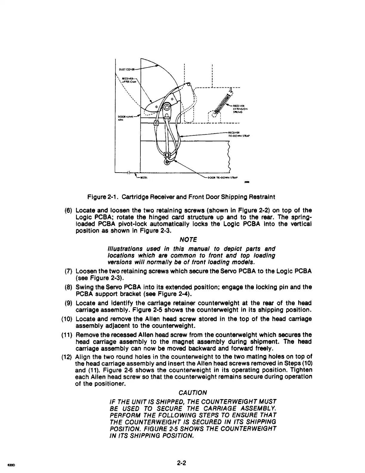
Figure 2-1. cartridge Receiver and Front Door Shipping Restraint
(6)
Locate and loosen the two retaining screws (shown in Figure
2-2)
on
top
of
the
Logic PCBA; rotate the hinged card structure up and to the rear. The sprlng-
loadad PCBA pivot-lock
automatically locks the Logic
PCBA
Into the vertical
position as shown
In
Figure 2-3.
NOTE
illustrations
used
in this manual
to
depict parts and
locations which
are
common
to
front and
top
loading
versions
will normally
be
of
front loading models.
(7)
Loosen the two retaining screws which secure the Servo PCBA to the
logic
PCBA
(see Figure 2-3).
(8) Swing the Servo PC8A Into Its extended position; engage the locking pin
and
the
PCBA support bracket
(see Figure 2-4).
(9)
Locate and identify the carriage retainer counterweight at the rear
of
the
head
carriage assembly. Figure
2-5
shows the counterweight in Its shipping position.
(10)
Locate and remove the Allen head screw stored in the top
of
the head carriage
assembly adjacent
to
the counterweight.
(11)
Remove the recessed Allen head screw from the counterweight which secures the
head carriage assembly
to
the magnet assembly during shipment. The head
carriage assembly can now
be
movad backward and forward freely.
(12)
Align the two round holes in the counterweight to the two mating holes on top
of
the
head
carriage assembly and insert the Allen head screws removed in Steps
(10)
and
(11).
Figure
2-6
shows the counterweight in
its
operating position. Tighten
each Allen head screw so that the counterweight remains secure during operation
of
the positioner.
CAUTION
IF
THE
UNIT
IS SHIPPED, THE COUNTERWEIGHT MUST
BE USED
TO
SECURE THE CARRIAGE ASSEMBLY.
PERFORM
THE FOLLOWING STEPS
TO
ENSURE THA T
THE COUNTERWEIGHT IS SECURED
IN
ITS SHIPPING
POSITION.
FIGURE
2-5
SHOWS THE COUNTERWEIGHT
IN
ITS SHIPPING POSITION.
2-2