81
GENERAL
APPENDIXB
FAULT-ISOLATION
PROCEDURES
Appendix B contains troubleshooting procedures which can be used as
an
aid in fault
isolation. The required test equipment for use with these troubleshooting procedures
Is
listed
in Paragraph B2. The Troubleshooting Procedure chart appears in Paragraph
83
as
Table B-2.
All references
to
paragraph numbers preceded by the letter B refer
to
paragraphs In this
Appendix, as
do
references
to
figures and tables. All references to the manual refer
to
PERTEC
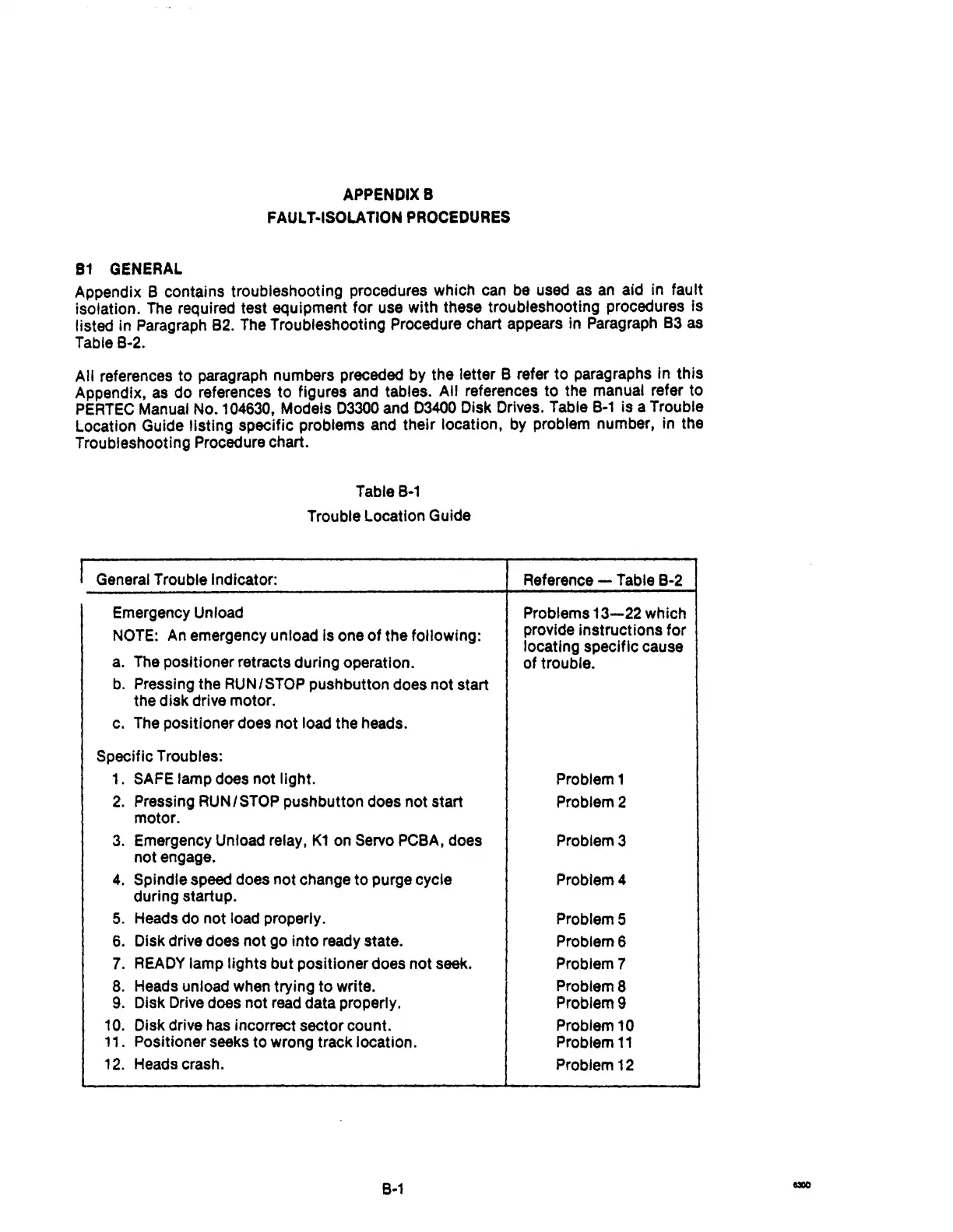
Manual No. 104630, Models 03300 and 03400 Disk Drives. Table
B-1
is a Trouble
Location Guide listing specific problems and their location, by problem number, in the
Troubleshooting Procedure chart.
Table
B-1
Trouble Location Guide
I General Trouble Indicator:
Emergency Unload
NOTE:
An
emergency unload
Is
one
of
the following:
a. The pOSitioner retracts during operation.
b.
Pressing the RUN/STOP pushbutton does not start
the disk drive motor.
c. The positioner does not load the heads.
Specific Troubles:
1.
SAFE lamp does not light.
2.
Pressing RUN/STOP pushbutton does not start
motor.
3.
Emergency Unload relay,
K1
on Servo PCBA, does
not engage.
4.
Spindle speed does not change to purge cycle
during startup.
5.
Heads do not load properly.
6. Disk drive does not go into ready state.
7.
READY
lamp lights but positioner does
not
seek.
8. Heads unload when trying
to
write.
9.
Disk Drive does not read data properly.
10. Disk drive has incorrect sector count.
11. Positioner seeks
to
wrong track location.
12. Heads crash.
8-1
Reference - Table B-2
Problems
13-22
which
provide Instructions
for
locating specific cause
of trouble.
Problem 1
Problem 2
Problem 3
Problem 4
Problem 5
ProblemS
Problem 7
Problem 8
Problem 9
Problem
10
Problem
11
Problem 12