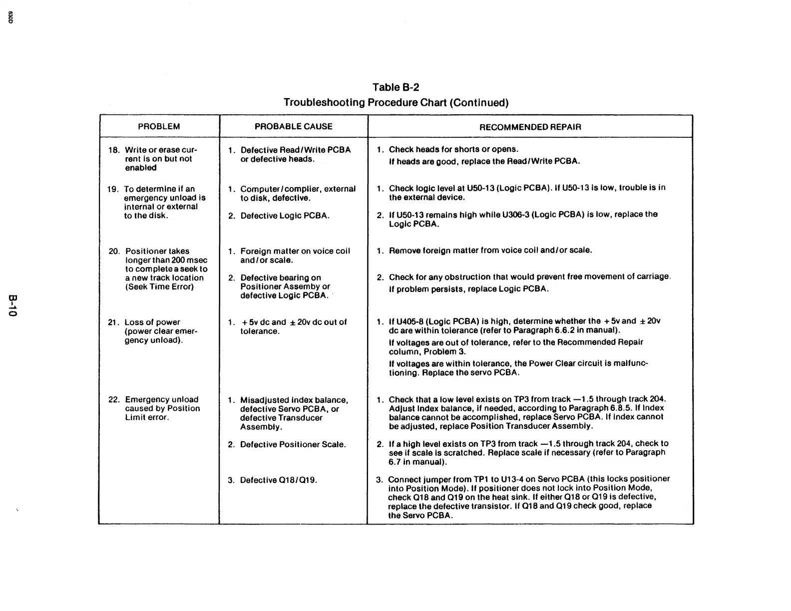
Table B-2
Troubleshooting Procedure Chart (Continued)
PROBLEM PROBABLE CAUSE
RECOMMENDED REPAIR
18.
Write
or
erase cur-
1.
Defective Read/Write PCBA
1.
Check heads for shorts
or
opens.
rent
is
on but not
or defective heads.
If
heads are good, replace the Read/Write PCBA.
enabled
19.
To determine if
an
1.
Computer
1 complier, external
1.
Check logic level at U50-13 (Logic PCBA).
If
USO-13Is low, trouble is in
emergency unload
is
to
disk, defective.
the external device.
internal or
external
to the disk.
2.
Defective Logic PCBA.
2.
If
U50-13 remains high while U306-3 (Logic PCBA) is low, replace the
LoglcPCBA.
20.
Positioner takes
1.
Foreign matter
on
voice coil
1.
Remove foreign matter from voice
coli
and/or
scale.
longer than
200
msec and 1 or scale.
to complete a seek to
a new track location
2.
Defective bearing on
2.
Check for any obstruction that would prevent free movement
of
carriage.
OJ
(Seek Time Error)
Positioner Assemby
or
If
problem persists, replace Logic PCBA.
defective Logic PCBA
..
,
.....
o
21.
Loss
of
power 1. +
5v
dc and ±
20v
dc
out
of
1.
It
U405-8 (Logic PCBA) Is high, determine whether the +
5v
and ±
20v
(power clear emer-
tolerance.
dc are
within
tolerance (refer
to
Paragraph 6.6.2 In manual).
gency unload).
If
voltages are
out
of
tolerance, refer
to
the Recommended Repair
column, Problem
3.
If
voltages are
within
tolerance, the Power Clear circuit Is malfunc-
tioning. Replace the servo
PCBA.
22.
Emergency unload
1. Mlsadjusted
Index balance, 1.
Check that a low level exists on TP3 from track
-l.S
through track 204.
caused
by Position
defective
Servo PCBA,
or
Adjust Index balance,
if
needed, according to Paragraph 6.8.5. If Index
Limit
error.
defective Transducer
balance cannot be accomplished, replace Servo PCBA. If Index cannot
Assembly.
be adjusted, replace Position Transducer Assembly.
2.
Defective Positioner Scale.
2.
If
a high level exists on TP3 from track
-1.5
through track
204,
check to
see if scale
Is scratched. Replace scale
If
necessary (refer to Paragraph
6.7 in manual).
3.
Defective
018/019.
3.
Connect jumper from
TP1
to U13-4 on Servo PCBA (this locks positioner
into
Position Mode).
If
positioner does not lock
into
Position Mode,
check
018
and
019
on the heat sink.
If
either
018
or
019
is
defective,
replace the defective transistor.
If
018
and
019
check good, replace
the Servo PCBA.