6300
EXTERNAL
-
COMMANDS _
PRESENT STATE
SIGNALS
USED
FOR
CONTROL
r AND INDICATION
STATE STORAGE
PRESENT STATES
EXTERNAL
COMMANDS+
STATE CONTROL
COMBINATIONAL LOGIC
AND
OUTPUT SIGNAL
COMBINATIONAL LOGIC
1-----
__
OUTPUT SIGNALS
FOR
CONTROL
1-----
__
AND INDICATION
DELAY
GENERATOR STATES
TIME REFERENCE
ICRYSTAL OSCILLATOR)
-
DELAY
GENERATOR
DELAY
CONTROL
NEXT STATE CONTROL
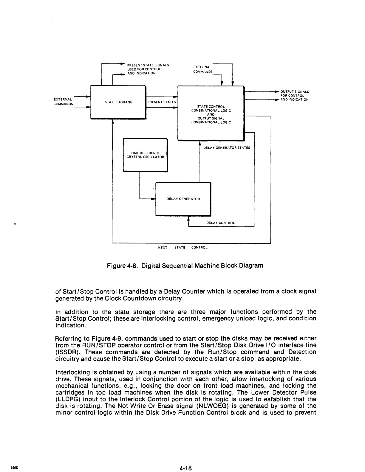
Figure 4-8. Digital Sequential Machine Block Diagram
of
Start/ Stop Control is handled by a Delay Counter which is operated from a clock signal
generated by the Clock Countdown circuitry.
In
addition to the statt.! storage there are three major functions performed
by
the
Start/Stop Control; these are interlocking control, emergency unload logic, and condition
indication.
Referring
to
Figure 4-9, commands used
to
start or stop the disks may be received either
from the
RUN/STOP operator control or from the
Start/Stop
Disk Drive
I/O
interface line
(ISSDR).
These commands
are
detected by the Run/Stop command and Detection
circuitry and cause the
Start/Stop
Control to execute a start
or
a stop,
as
appropriate.
Interlocking is obtained by using a number
of
signals which are available within the disk
drive. These
signals, used
in
conjunction with each other, allow interlocking of various
mechanical functions, e.g., locking the door on front load machines, and locking the
cartridges in top
load machines when the disk is rotating. The Lower Detector Pulse
(LLDPG) input to the Interlock Control portion
of
the logic is used to establish that the
disk
is rotating. The Not Write Or Erase signal (NLWOEG) is generated by some of the
minor
control logic within the Disk Drive Function Control block and is used to prevent
4-18