KENR6932 103
Disassembly and Assembly Section
d. Apply a small continuous bead of Tooling
(A) to outer sur
face (Y) of bearing (5). Place
accessory drive housing (8) on a suitable
support. Press the assembly of gear (4) and
bearings (3) a
nd (5) into the accessory drive
housing . Ensure that bearing (5) is against
the front face of the recess in accessory drive
housing (8).
Remove any excess sealant.
e. Install circlip (2) into the groove in accessory
drive housin
g (8). Ensure that circlip (2) is
correctly positioned in the groove.
2. Lightly lubr
icate a new O-ring seal (7) with Tooling
(B) and install the O-ring seal into the groove in
accessory drive housing (8).
3. Inspect the bore in the front housing for damage.
If necessary, replace the front housing. Refer to
Disassembl
y and Assembly, “Housing (Front)
- Remove” and Disassembly and Assembly,
“Housing (Front) - Install”.
4. Lightly lubricate bearing (3), bearing (5), and
gear (4) with clean engine lubricating oil. Install
the assemb
ly of the accessory drive to the front
housing.
5. Apply Tool
ing (C) to Allen head screws (1) and
(6). Install Allen head screws (6) to accessory
drive housing (8). Install Allen head screw (1) to
accessor
y drive housing (8).
6. Tighten the Allen head screws to a torque of
22 N·m (16
lb ft).
7. Ensure that there is tactile backlash between the
idler gea
r and the accessory drive gear.
i02654404
Crankca se Breather - Remo ve
(Unfiltered Breather)
Removal Procedure
Table 46
Required Tools
Tool
Part
Number
Part Description
Qty
A
-
Breather Tool 1
NOTICE
Keep all parts clean from contaminants.
Contaminants may cause rapid wear and shortened
component life.
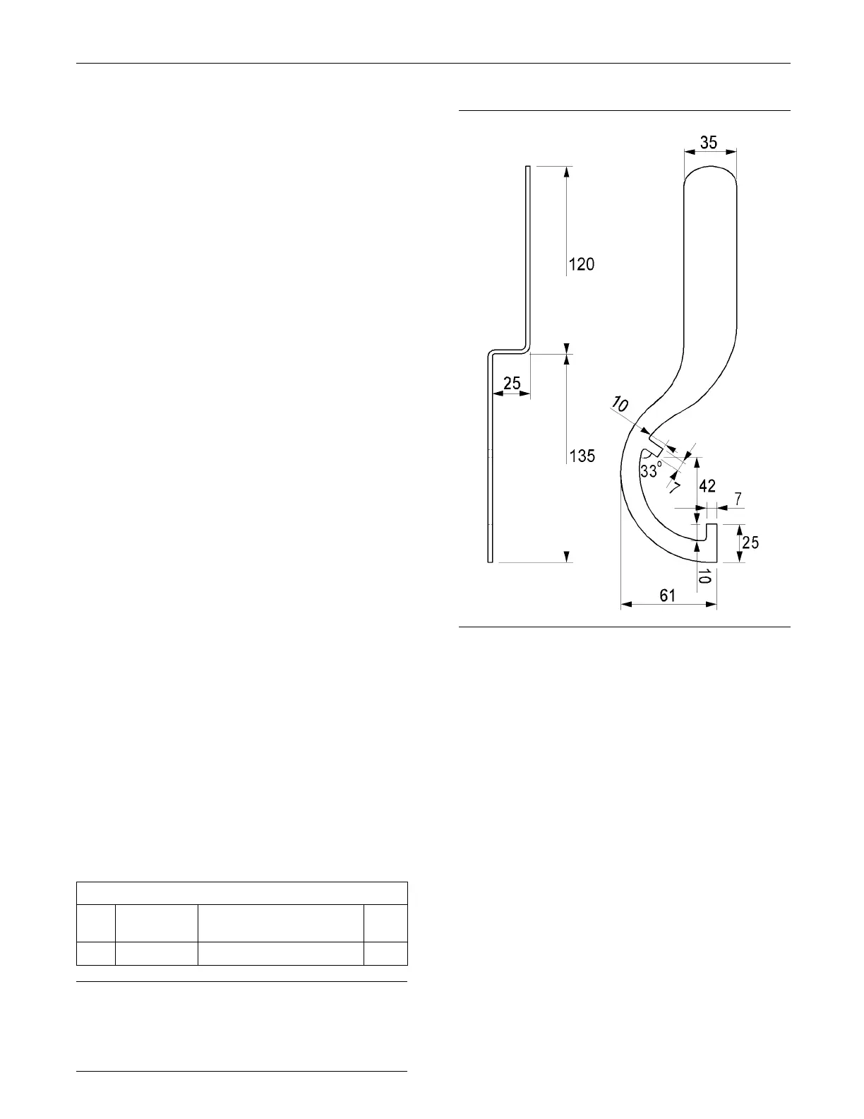
g01339595
Illustration 198
Breather tool
1. To remove the breather body, Tooling (A) must be
used. The tool should be fabricated from 3.1 mm
(1/8 inch) steel stock. The dimensions f or the tool
are given in Illustration 198. All dimensions are
showninmillimeters.

 Loading...


